

1466-V Vector Signal Generator
SKU : 1466-V Vector Signal Generator
![]() Product Overview
Product Overview
Ceyear 1466-V vector signal generator is created to meet the varied test requirements with top performance and functionality, especially in higher frequencies, wider bandwidths, higher signal spectral purity, higher output power, better EVM and high-precision synchronized multichannel applications. Also rich built-in functions such as analog modulation, digital modulation, fading simulation, and AWGN could bring more convenience to daily testing. Through integration with multi-scenario signal simulation software, complex style signals can be generated for general-purpose tests in different scenarios for wireless communication, radar and navigation. Friendly designed human-computer interaction, including graphics guided operation, web browser based remote control, power meter automatic connection and identification, SCPI command recording, as well as interface user customization could speed up the test operation. The Ceyear 1466-V vector signal generator is an ideal choice for high standard testing in components, modules, machines and systems.
![]() Features
Features
Excellent spectral purity, making cutting-edge testing easier
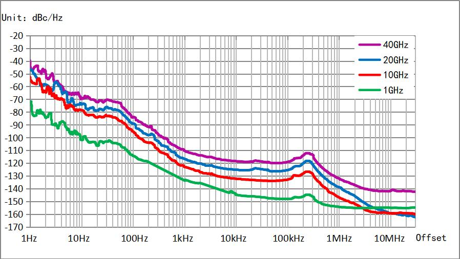
Ceyear 1466-V vector signal generator supports high spectral purity output signal, SSB phase noise: -145dBc/Hz @10kHz offset at 1GHz carrier, -132dBc/Hz @10kHz offset at 10GHz carrier, Wideband noise floor: -161dBc/Hz @30MHz offset at 20GHz carrier, spurious<-80dBc at 10GHz carrier, harmonics <-55dBc. The purer signal makes you no longer troubled by interfering signals when testing microwave and millimeter wave components, systems and OTA.
Large dynamic range and high accuracy power output
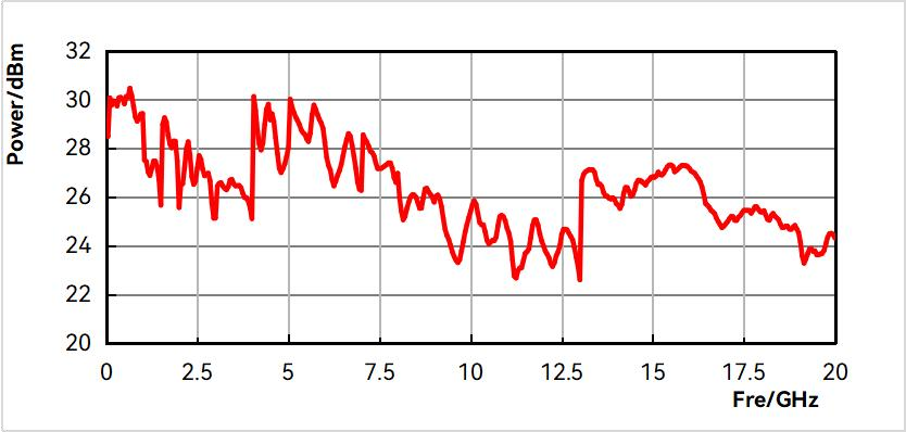
Ceyear 1466-V vector signal generator maximum output power(typ.): +27dBm @5GHz, +24dBm@ 20GHz, +25dBm @30GHz, +22dBm@ 60GHz. Minimum settable output power can up to -150dBm,dynamic range of output power can reach 170dB. It has excellent power accuracy specifications:<0.5dB below 20GHz(typ).
2GHz RF modulation bandwidth
Ceyear 1466-V vector signal generator can provide a maximum 2GHz RF modulation bandwidth. According to different application scenarios, it supports flexible selection of 500MHz, 1GHz and 2GHz bandwidth. When using an external broadband baseband signal input, the RF modulation bandwidth is up to 5GHz. Regardless of the current 5G communication or the future 6G communication, the superior modulation bandwidth performance can easily meet the test challenges.
Excellent vector modulation accuracy
Ceyear 1466-V vector signal generator has excellent vector modulation accuracy, QPSK modulation EVM measured value 0.4%(2GHz carrier) . 5GNR ACPR (typical value, <-55dBc@2GHz carrier, <-45dBc@42.5GHz carrier). The signal generator is capable of performing performance evaluation in communication equipment research and development and communication equipment performance testing in production lines.
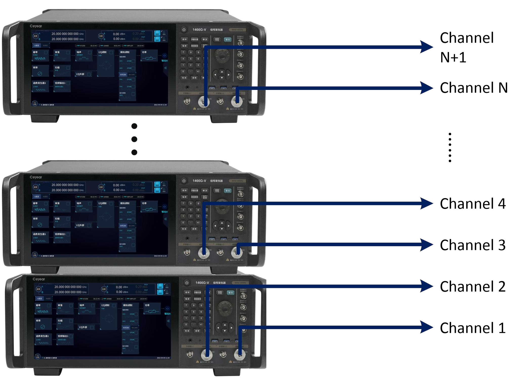
Multi-machine cascade for multi-source phase reference excitation
Support multi-machine cascading, providing solutions for MIMO, beamforming, and signal diversity testing.
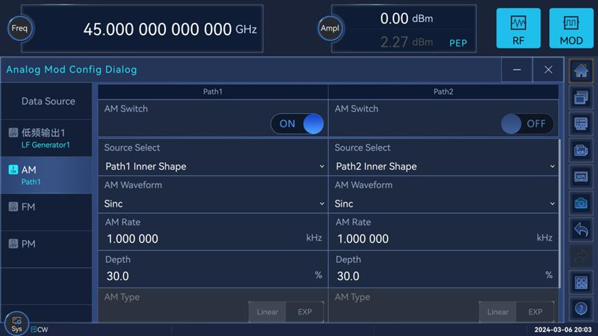
Full range of analog modulation
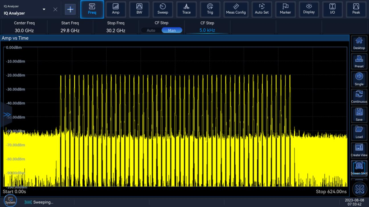
Amplitude modulation, frequency modulation, phase modulation and pulse modulation are supported. It has complex pulse modulation functions such as double pulse, pulse train, PRF jittering, PRF staggering, and PRF sliding.
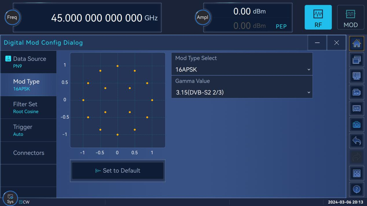
Comprehensive standard digital modulation styles
Generation of up to 30+ digital standard modulation signals (PSK, FSK, QAM, APSK), covering all important frequency bands and modulation styles for digital communications.
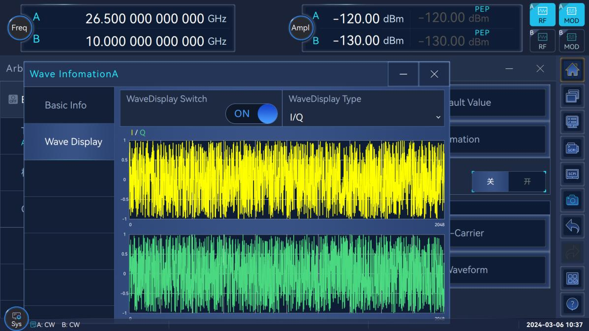
Arbitrary wave playback
Support user-defined arbitrary waveform data variable sampling rate playback function. With the convenient baseband preview function, it is convenient for you to verify the correctness of the data in the time domain and frequency domain at the first time.
Multicarrier signal generation
Support continuous wave multi-tone and complex multi-carrier modulation functions to make complex signal scene construction easier.
Multiple types of noise addition methods
Support pure noise, additive Gaussian noise, continuous wave interference and other noise adding functions.
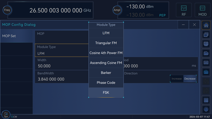
Intra-pulse modulation
Supports multiple types of intrapulse modulation including linear frequency modulation, Barker code, phase modulation code, etc.
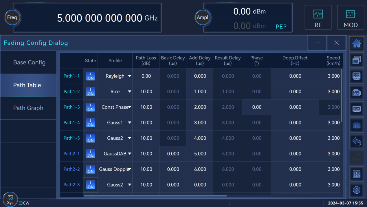
Real-time fading simulation
Maximum 20 fading paths, supporting fading types such as pure Doppler, Rayleigh, Rice, Rayleigh + lognormal, etc., supporting preset fading scene modes, and simulating fading channel models defined by 3GPP.
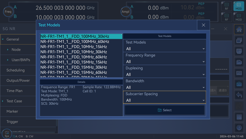
Mobile Communication Signal Simulation
For the development and production of mobile communication base stations or terminals, as well as the radio frequency conformance test necessary for the verification and approval of mobile communication equipment network access, the Ceyear 1466-V signal generator supports standard protocol signals through embedded more than 600 TestModel/FRC including 5G NR one-click simulation. At the same time, with the mobile communication signal simulation software, it can realize flexible editing and simulation of various communication protocol signals.
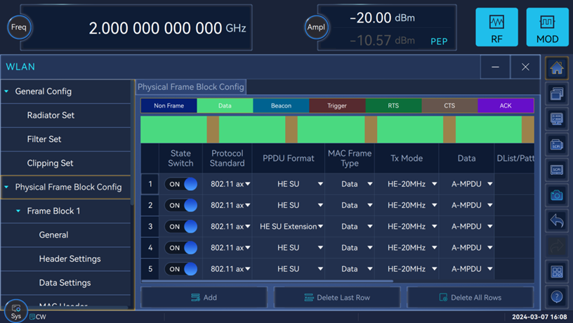
WLAN Signal Simulation
For the development, production and testing of wireless communication terminals, it has 802.11a/b/g/n/ac/ax wireless connection PPDU, MPDU, A-MPDU and other signal simulations, and supports physical frames composed of multiple PPDUs with different modulation and coding methods Block signal simulation.
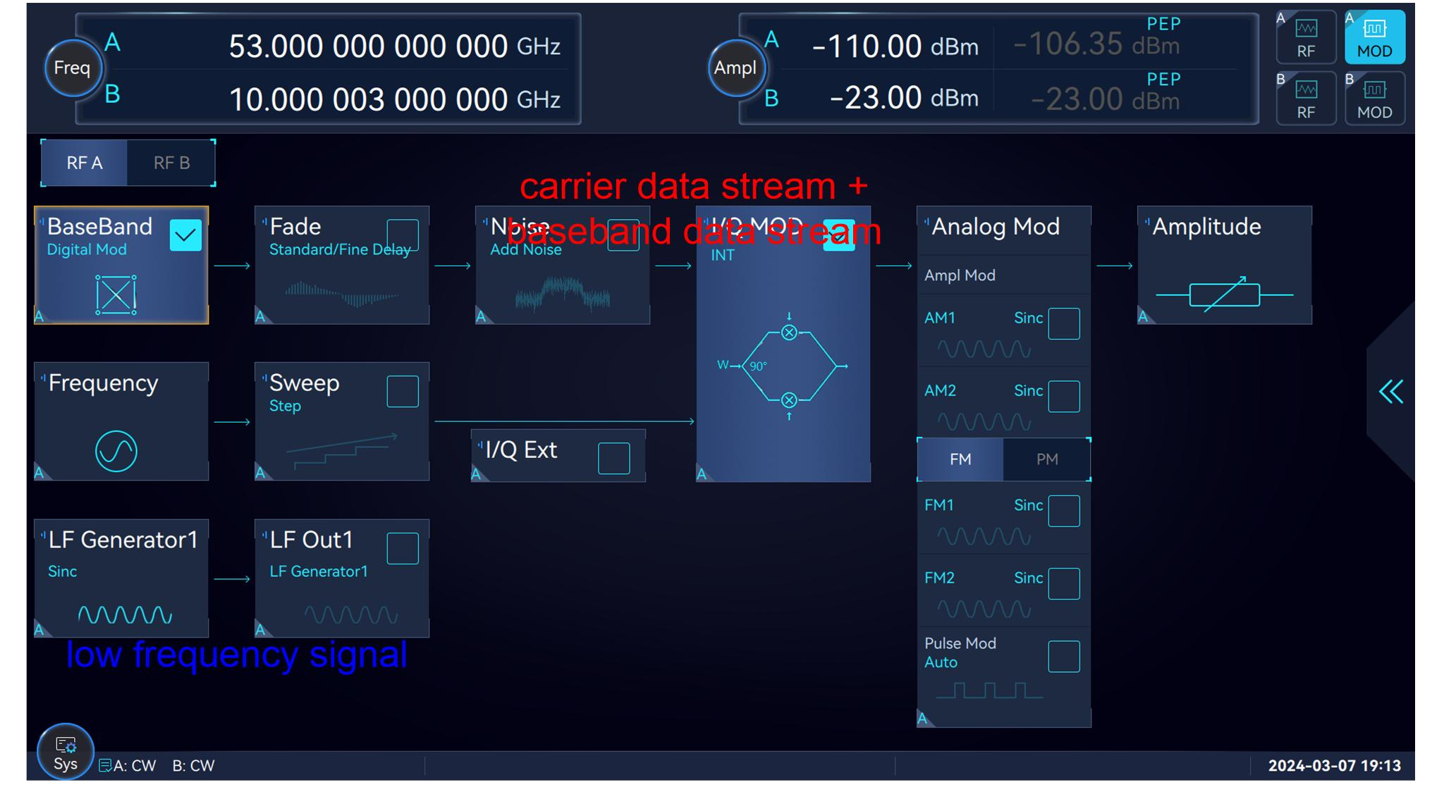
Touchable graphic guide interaction
The 11.6-inch high-resolution touch screen is used to clearly display the main parameters and instrument status information, and with the signal flow diagram guidance interface, the display is more intuitive and the interaction is more friendly.
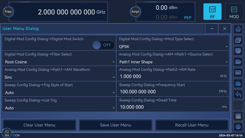
Flexible editable user control interface
Support user-defined menus, tailor-made personalized user control interface according to test habits, realize multi-functional operations in one window, and avoid the trouble of too deep menus and repeated searches.
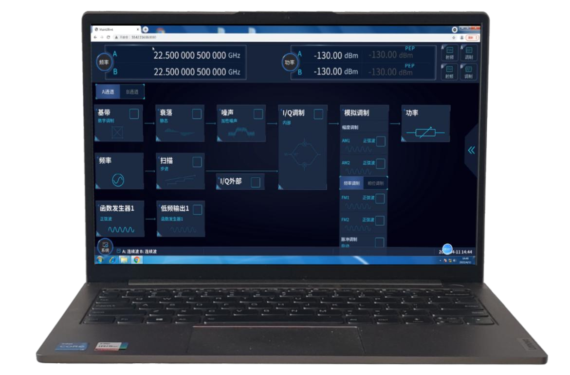
Support cross-platform client control
Cross-platform client and browser access control. Support multiple clients to connect at the same time, and the working status of the instrument is refreshed synchronously. Supports web browser access control for mobile devices.
![]() specifications
specifications
| Frequency characteristics | ||||||||
| Frequency | 1466C-V:6kHz to 13GHz1466D-V: 6kHz to 20GHz1466E-V: 6kHz to 33GHz1466G-V: 6kHz to 45GHz1466H-V: 6kHz to 53GHz1466L-V: 6kHz to 67GHz | Frequency range | N1 | |||||
| 6kHz≤f≤10MHz | - | |||||||
| 10MHz<f≤50MHz | - | |||||||
| 50MHz<f≤62.5MHz | 1/256 | |||||||
| 62.5MHz<f≤125MHz | 1/128 | |||||||
| 125MHz<f≤250MHz | 1/64 | |||||||
| 250MHz<f≤500MHz | 1/32 | |||||||
| 500MHz<f≤1GHz | 1/16 | |||||||
| 1GHz<f≤2GHz | 1/8 | |||||||
| 2GHz<f≤4GHz | 1/4 | |||||||
| 4GHz<f≤8GHz | 1/2 | |||||||
| 8GHz<f≤20GHz | 1 | |||||||
| 20GHz<f≤40GHz | 2 | |||||||
| 40GHz<f≤67GHz | 4 | |||||||
| Resolution | 0.001Hz | |||||||
| Switching speed | <15ms | |||||||
| Aging rate(typ.) | ±5×10 -10 /day after 30 days warm-up | |||||||
| Reference Output | Frequency | 10MHz | ||||||
| Power | >+4dBm, to 50Ω load | |||||||
| Reference Input | Frequency | 1 to 100MHz,step:1Hz | ||||||
| Power | -5dBm to +10dBm,impedance: 50Ω | |||||||
| Sweep properties | ||||||||
| Sweep mode | Step sweep List sweep Ramp(analog) sweep(option S15) Power sweep(option S16) | |||||||
| Ramp(analog) sweep | Maximum sweep rate | f>4GHz | 400MHz/ms | |||||
| Frequency accuracy | ±0.05% of span (at 100ms sweep time, for sweep spans less than maximum values given above) | |||||||
| Power characteristics | ||||||||
| Minimum output power | Model | Standard | Option H01-90/120/130 | |||||
| 1466C/D/E/G(-V) | -10dBm(settable -20dBm) | Option H01-130: -120.0dBm(settable -150dBm) | ||||||
| 1466H/L(-V) | -10dBm(settable -20dBm) | Option H01-90:-90.0dBm(settable -110dBm) | ||||||
| Option H01-120: -90.0dBm(csettable -140dBm) | ||||||||
| Maximum output power(CW, 25±10°C) | 1466C-V | |||||||
| Configuration | Standard | Programmable step attenuator Option H01-130/B130 | High output power (option H05- 13/B13) | High output power and programmable step attenuator (option H01-130+H05-13; H01-B130+H05-B13) | ||||
| FrequencyRange | ||||||||
| 6kHz≤f≤50MHz | ≥+15.0 | ≥+15.0 | ≥+15.0 | ≥+15.0 | ||||
| 50MHz<f≤13GHz | ≥+15.0 | ≥+15.0 | ≥+20.0 | ≥+20.0 | ||||
| 1466D-V | ||||||||
| Configuration | Standard | Option H01- | Option H05- | Option H01-130+H05-20; H01-B130+H05-B20 | ||||
| Frequency range | 130/B130 | 20/B20 | ||||||
| 6kHz≤f≤50MHz | ≥+15.0 | ≥+15.0dBm | ≥+15.0dBm | ≥+15.0dBm | ||||
| dBm | ||||||||
| 50MHz<f≤20GHz | ≥+15.0 | ≥+15.0dBm | ≥+20.0dBm | ≥+20.0dBm | ||||
| dBm | ||||||||
| 1466E | ||||||||
| Configuration | Standard | Programmable step attenuator Option H01-130/B130 | High output power (option H05-20,H05-B20 | High output power and programmable step attenuator(option H01-130,H05-20,H01-B130,H05-B20) | ||||
| Frequencyrange | ||||||||
| 6kHz≤f≤50MHz | ≥+8.0 | ≥+8.0 | ≥+15.0 | ≥+15.0 | ||||
| 50MHz<f≤6GHz | ≥+12.0 | ≥+12.0 | ≥+20.0 | ≥+20.0 | ||||
| 6GHz<f≤18GHz | ≥+12.0dBm | ≥+12.0 | ≥+18.0 | ≥+18.0 | ||||
| 18GHz<f≤30GHz | ≥+12.0 | ≥+12.0 | ≥+17.0 | ≥+17.0 | ||||
| 30GHz<f≤33GHz | ≥+12.0 | ≥+12.0 | ≥+18.0 | ≥+18.0 | ||||
| 1466G-V | ||||||||
| Configuration | Standard | Programmable step attenuatorOption H01-130, H01-B130 | High output power (option H05-45,H05-B45 | High output power and programmable step attenuator(option H01-130,H05-45,H01-B130,H05-B45) | ||||
| FrequencyRange | ||||||||
| 6kHz≤f≤50MHz | ≥+8.0 | ≥+8.0 | ≥+15.0 | ≥+15.0 | ||||
| 50MHz<f≤6GHz | ≥+12.0 | ≥+12.0 | ≥+20.0 | ≥+20.0 | ||||
| 6GHz<f≤18GHz | ≥+12.0 | ≥+12.0 | ≥+18.0 | ≥+18.0 | ||||
| 18GHz<f≤30GHz | ≥+12.0 | ≥+12.0 | ≥+17.0 | ≥+17.0 | ||||
| 30GHz<f≤40GHz | ≥+12.0 | ≥+12.0 | ≥+18.0 | ≥+18.0 | ||||
| 40GHz<f≤45GHz | ≥+12.0 | ≥+12.0 | ≥+14.0 | ≥+13.0 | ||||
| 1466H-V | ||||||||
| Configuration | Standard | rogrammable step attenuatorOption H01-90/120, H01-B90/120 | High output power (option H05-53,H05-B53 | High output power and programmable step attenuator(option H01-90/120+H05-53,H01-B90/120+H05-B53 | ||||
| FrequencyRange | ||||||||
| 6kHz≤f≤50MHz | ≥+8.0 | ≥+8.0 | ≥+12.0 | ≥+12.0 | ||||
| 50MHz<f≤35GHz | ≥+8.0 | ≥+8.0 | ≥+17.0 | ≥+16.0 | ||||
| 20GHz<f≤40GHz | ≥+8.0 | ≥+8.0 | ≥+15.0 | ≥+13.0 | ||||
| 40GHz<f≤53GHz | ≥+8.0 | ≥+8.0 | ≥+20.0 | ≥+18.0 | ||||
| 1466L-V | ||||||||
| Configuration | Standard | Programmable step attenuatorOption H01-90/120,H01-B90/B120 | High output power (option H05-67,H05-B67 | High output power and programmable step attenuator(option H01-90/120+H05-53, H01-B90/120+H05-B53) | ||||
| Frequency Range | ||||||||
| 6kHz≤f≤50MHz | ≥+8.0 | ≥+8.0 | ≥+12.0 | ≥+12.0 | ||||
| 50MHz<f≤35GHz | ≥+8.0 | ≥+8.0 | ≥+17.0 | ≥+16.0 | ||||
| 35GHz<f≤40GHz | ≥+8.0 | ≥+8.0 | ≥+15.0 | ≥+13.0 | ||||
| 40GHz<f≤53GHz | ≥+8.0 | ≥+8.0 | ≥+20.0 | ≥+18.0 | ||||
| 53GHz<f≤65GHz | ≥+8.0 | ≥+8.0 | ≥+18.0 | ≥+16.0 | ||||
| 65GHz<f≤67GHz | ≥+8.0 | ≥+8.0 | ≥+15.0 | ≥+12.0 | ||||
| Level accuracy (25±10°C) | Standard | |||||||
| Power(dBm) Frequency | -10dBm<P≤+10dBm | +10dBm<P≤+25dBm | +25dBm<P | |||||
| 6kHz≤f≤100kHz | ±1.0dB | ±1.0dB | — | |||||
| 50MHz<f≤3GHz | ±0.5dB | ±0.5dB | ±1.0dB | |||||
| 3GHz<f≤20GHz | ±0.9dB | ±0.9dB | ±1.2dB | |||||
| 20GHz<f≤40GHz | ±1.0dB | ±1.0dB | — | |||||
| 40GHz<f≤50GHz | ±1.3dB | ±1.3dB | — | |||||
| 50GHz<f≤67GHz | ±1.8dB | ±1.8dB | — | |||||
| H01-130/120/90/50/B130 programmable step attenuator option | ||||||||
Power(dBm) Frequency | +120dBm<P≤-90dBm | -90dBm<P≤-50dBm | -50dBm<P≤+10dBm | +10dBm<P≤+25dBm | +25dBm<P | |||
| 6kHz≤f≤50kHz | — | ±1.5dB | ±1.0dB | ±1.0dB | — | |||
| 50MHz<f≤3GHz | ±1.2dB | ±0.7dB | ±0.5dB | ±0.5dB | ±1.0dB | |||
| 3GHz<f≤20GHz | ±1.8dB | ±0.9dB | ±0.9dB | ±0.9dB | ±1.2dB | |||
| 20GHz<f≤40GHz | — | ±1.2dB | ±1.0dB | ±1.0dB | — | |||
| 40GHz<f≤50GHz | — | ±1.5dB | ±1.3dB | ±1.3dB | — | |||
| 50GHz<f≤67GHz | — | ±2.0dB | ±1.8dB | ±1.8dB | — | |||
| Power resolution | 0.01dB | |||||||
| Temperature stability | 0.02dB/°C (typ) | |||||||
| Output impedance | 50Ω(Nom.) | |||||||
| VSWR(internal leveled)(typ) | 100kHz≤f≤20GHz | <1.6 | ||||||
| 20GHz<f≤40GHz | <1.8 | |||||||
| 40GHz<f≤67GHz | <2.0 | |||||||
| Maximum reverse power | 0.5W(0V DC)(nom) | |||||||
| Spectral purity characteristics | ||||||||
| Harmonics (dBc at +10dBm or maximum specified output power, whichever is lower) | Frequency | Standard | ||||||
| 6kHz≤f≤3GHz | <-30dBc | |||||||
| 3GHz<f≤67GHz | <-55dBc | |||||||
| Sub-harmonics(at +10dBm or maximum specified output power, whichever is lower) | 100kHz≤f≤20GHz | <-80dBc | ||||||
| 20GHz<f≤40GHz | <-60dBc | |||||||
| 40GHz<f≤67GHz | <-50dBc | |||||||
| Non-harmonics(dBc at 0dBm, for offset >3kHz) | Frequency | Standard /Option H04-1 | Option H04-2 | |||||
| 6kHz≤f≤250MHz | <-58dBc | <-68dBc | ||||||
| 250MHz<f≤4GHz | <-70dBc | <-80dBc | ||||||
| 4GHz<f≤10GHz | <-70dBc | <-80dBc | ||||||
| 10GHz<f≤20GHz | <-64dBc | <-74dBc | ||||||
| 20GHz<f≤40GHz | <-58dBc | <-68dBc | ||||||
| 40GHz<f≤67GHz | <-45dBc | <-45dBc | ||||||
| SSB phase noise (dBc/Hz, at +10dBm or maximum specified output power, whichever is lower) | Offset from carrier | 10Hz | 100Hz | 1kHz | 10kHz | 100kHz | 1MHz | 10MHz |
| Standard phase noise | ||||||||
| 100MHz | — | <-110 | <-128 | <-134 | <-138 | — | — | |
| 250MHz<f≤500MHz | — | <-108 | <-126 | <-132 | <-136 | — | — | |
| 0.5 GHz<f≤1GHz | — | <-103 | <-121 | <-130 | <-130 | — | — | |
| 1 GHz<f≤2GHz | — | <-97 | <-117 | <-124 | <-124 | — | — | |
| 2 GHz<f≤4GHz | — | <-92 | <-111 | <-118 | <-118 | — | — | |
| 4GHz<f≤10GHz | — | <-85 | <-105 | <-110 | <-110 | — | — | |
| 10GHz<f≤20GHz | — | <-79 | <-98 | <-104 | <-104 | — | — | |
| 20GHz<f≤40GHz | — | <-73 | <-91 | <-98 | <-98 | — | — | |
| 40GHz<f≤67GHz | — | <-68 | <-85 | <-92 | <-92 | — | — | |
| H04-1 low phase noise option | ||||||||
| 100MHz | — | <-118 | <-141 | <-148 | <-148 | — | — | |
| 250MHz<f≤500MHz | — | <-111 | <-130 | <-145 | <-143 | — | — | |
| 0.5 GHz<f≤1GHz | — | <-105 | <-124 | <-140 | <-138 | — | — | |
| 1 GHz<f≤2GHz | — | <-100 | <-118 | <-134 | <-132 | — | — | |
| 2 GHz<f≤4GHz | — | <-93 | <-113 | <-128 | <-126 | — | — | |
| 4GHz<f≤10GHz | — | <-85 | <-105 | <-120 | <-118 | — | — | |
| 10GHz<f≤20GHz | — | <-79 | <-99 | <-114 | <-112 | — | — | |
| 20GHz<f≤40GHz | — | <-73 | <-93 | <-108 | <-106 | — | — | |
| 40GHz<f≤67GHz | — | <-67 | <-87 | <-103 | <-101 | — | — | |
| H04-2 ultra low phase noise option | ||||||||
| 100MHz | <-102 | <-118 | <-141 | <-148 | <-148 | <-148 | <-148 | |
| 250MHz<f≤500MHz | <-92 | <-112 | <-135 | <-146 | <-148 | <-150 | <-150 | |
| 0.5GHz<f≤1GHz | <-90 | <-110 | <-134 | <-144 | <-147 | <-150 | <-150 | |
| 1GHz<f≤2GHz | <-88 | <-104 | <-127 | <-138 | <-142 | <-148 | <-148 | |
| 2 GHz<f≤4GHz | <-82 | <-99 | <-122 | <-135 | <-136 | <-146 | <-148 | |
| 4GHz<f≤10GHz | <-77 | <-91 | <-115 | <-128 | <-128 | <-140 | <-154 | |
| 10GHz<f≤20GHz | <-71 | <-85 | <-109 | <-122 | <-122 | <-134 | <-152 | |
| 20GHz<f≤40GHz | <-63 | <-79 | <-99 | <-116 | <-116 | <-128 | <-142 | |
| 40GHz<f≤67GHz | <-57 | <-73 | <-94 | <-110 | <-110 | <-122 | <-136 | |
| Modulation characteristics | ||||||||
| Frequency modulation (50MHz<f≤50GHz,Option S11 | Maximum deviation:N×20MHz(N: YO harmonic number) Accuracy(at 1kHz, N×20kHz≤deviation<N×800kHz): <± (2.5%× set frequency offset +20Hz) Modulation rate(3dB bandwidth, N×500kHz frequency offset)):DC-10MHz Distortion(at 1kHz, N×20kHz≤deviations<N×800kHz):<1% | |||||||
Phase modulation (50MHz<f≤50GHz,Option S11) | Maximum deviation: Normal mode:N×20.0rad(N: YO harmonic number) | |||||||
Amplitude modulation | Maximum depth:>90% | |||||||
| Pulse modulation (f>50MHz, option S13 will cover option S12) | Option S12: Pulse modulation | |||||||
| On/off ratio | >80dB | |||||||
| Rise/fall times | <20ns | |||||||
| Repetition frequency | 0Hz to 25MHz | |||||||
| Minimum pulse width | 0.1μs | |||||||
| Option S13: Narrow Pulse modulation | ||||||||
| On/off ratio | >80dB | |||||||
| Rise/fall times | <10ns | |||||||
| Repetition frequency | 0Hz to 25MHz | |||||||
| Minimum pulse width | 20ns | |||||||
LF out/Function generator(option S14) | Support frequency/phase modulation, amplitude modulation output Waveform: sina, square, triangle, sawtooth, noise, double sine, sweep sine Frequency range: DC to 10MHz for sine, double sine, sweep sine waveform; 0.1Hz to 1MHz for square, triangle, swatooth waveform. Frequency resolution:0.1Hz Low frequency output:amplitude: 0 to 5Vpp(nom), into 50Ω load Basic modulation types(symbol rate 4 Msym/s,root Nyquist filter,α=0.3,QPSK format,f>100MHz): 100MHz<f≤4GHz <0.8% 4GHz<f≤20GHz <1.0% 20GHz<f≤40GHz <1.2% 40GHz<f≤67GHz <1.4% CDMA(symbol rate 3.84 Msym/s,root Nyquist filter,α=0.22,QPSK format): <0.7% (2GHz) 5GNR:(Test Model 3.1a,100MHz,256QAM,30kHz SCS,Option S01): <0.85% (100MHz,3.5GHz) <1.0% (100MHz,10GHz) <1.2% (100MHz,28GHz) <1.8% (100MHz,42.5GHz) | |||||||
Adjacent Channel Power Ratio(ACPR,after calibration ,25℃±10℃) | CDMA:(symbol rate 3.84 Msym/s,root Nyquist filter,α=0.22,QPSK format) >64dBc (2GHz) 5GNR:(Test Model 3.1a,100MHz,256QAM,30kHz SCS,option S01) 1466C/D/E/F-V: >52dBc (100MHz,3.5GHz,0dBm) >51dBc (100MHz,10GHz,0dBm) >48dBc (100MHz,28GHz,0dBm) >42dBc (100MHz,42.5GHz,0dBm) 1466H/L-V: >52dBc (100MHz,3.5GHz,0dBm) >51dBc (100MHz,10GHz,0dBm) >46dBc (100MHz,28GHz,+5dBm) >41dBc (100MHz,42.5GHz,+5dBm) | |||||||
Internal modulation bandwidth | (Carrier:900MHz, 2.6GHz, 3.5GHz, 10GHz, 28GHz, 42.5GHz, option S01/02) H31-500/H31-B500 option:500MHz(Multitone,number of tones:51,Frequency interval:10MHz,frequency response:<3.0dB); H31-1000/H31-B1000 option:1GHz(Multitone,number of tones:51, carrier:≥2.6GHz,frequency interval: 20MHz,frequency response: <4.0dB); H31-2000/H31-B2000 option:2GHz(Multitone,number of tones:51 carrier: ≥3.5GHz,frequency interval: 40MHz,frequency response: <5.0dB). (carrier: 10GHz, 28GHz,42.5GHz) standard:2GHz(ALC off,input 500mVPP sine to channel I,frequency response: ±5.0dB); H33/H33-B:5GHz(f>20GHz,ALC off,input 500mVPP sine to channel I,frequency response: ±8.0dB). | |||||||
Internal baseband signal generator | Channel:2(I and Q) single real-time repeat trigger, high gating valid, low gating valid. | |||||||
| General characteristics | ||||||||
| RF Output Port | 1466C/D(-V):3.5mm(Male),Impedance 50Ω 1466E/G(-V):2.4mm(Male),Impedance 50Ω 1466H/L(-V):1.85mm(Male),Impedance 50Ω | |||||||
| Dimensions (W×H×D) | 475mm×193mm×620mm(Includes handle and protective bottom corner) 426mm×177mm×500mm(Excludes handle and protective bottom corner) | |||||||
| Weight | <35kg(weight depend on product model and option) | |||||||
| Power requirements | 100 to 120VAC,50 to 60Hz or 200 to 240VAC,50 to 60Hz(adaptive power supply) | |||||||
| Power Consumption | <700W | |||||||
| Temperature Range | Operating temperature range:0°C to +50°C; Storage temperature range:-40°C to +70°C | |||||||
![]() Host Model
Host Model
| Numbering | Name | Describe |
| 1466C-V | Signal Generator | 6kHz to 13GHz |
| 1466D-V | Signal Generator | 6kHz to 20GHz |
| 1466E-V | Signal Generator | 6kHz to 33GHz |
| 1466G-V | Signal Generator | 6kHz to 45GHz |
| 1466H-V | Signal Generator | 6kHz to 53GHz |
| 1466L-V | Signal Generator | 6kHz to 67GHz |
![]() Option Model
Option Model
| Numbering | Name | Describe | Optional |
| 1466-H01-130 | 130dB programmable step attenuator | To expand output power dynamic range for 1466C/D/E/G-V | |
| 1466-H01-120 | 120dB programmable step attenuator | To expand output power dynamic range for 1466H/L-V | |
| 1466-H01-90 | 90dB programmable step attenuator | To expand output power dynamic range for 1466H/L-V | |
| 1466-H01-B130 | Channel B 130dB programmable step attenuator | To expand Channel B output power dynamic range for 1466C/D-V, Requires option 1466-H11-B13/B20/BV13/BV20 | |
| 1466-H04-1 | Low phase noise | Improved phase noise performance,10GHz@10kHz:-120dBc/Hz. | |
| 1466-H04-2 | Ultra low phase noise | Improved phase noise performance,10GHz@10kHz:-128dBc/Hz. | |
| 1466-H04-B1 | Channel B low phase noise | Improved Channel B phase noise performance,10GHz@10kHz:-120dBc/Hz, Regarding options 1466-H11-B13/B20/BV13/BV20. | |
| 1466-H04-B2 | Channel B ultra low phase noise | Improved Channel B phase noise performance,10GHz@10kHz:-128dBc/Hz, Regarding options 1466-H11-B13/B20/BV13/BV20. | |
| 1466-H05-13 | 13GHz High output power | Improve maximum output power for 1466C-V | |
| 1466-H05-20 | 20GHz High output power | Improve maximum output power for 1466D-V | |
| 1466-H05-33 | 33GHz High output power | Improve maximum output power for 1466E-V | |
| 1466-H05-45 | 45GHz High output power | Improve maximum output power for 1466G-V | |
| 1466-H05-53 | 53GHz High output power | Improve maximum output power for 1466H-V | |
| 1466-H05-67 | 67GHz High output power | Improve maximum output power for 1466L-V | |
| 1466-H05-B13 | 13GHz Channel B High output power | Improve Channel B maximum output power for 1466C-V,Option 1466-H11-B13/BV13 need to be configured | |
| 1466-H05-B20 | 20GHz Channel B High output power | Improve Channel B maximum output power for 1466D-V,Option 1466-H11-B20/BV20 need to be configured | |
| 1466-H11-B13 | 13GHz Channel B | Add Channel B,output 6kHz to 13GHz vector signal for 1466D-V | |
| 1466-H11-B20 | 20GHz Channel B | Add Channel B, Output 6kHz to 20GHz Vector signal for 1466D-V | |
| 1466-H31-500 | 500MHz modulation bandwidth | Internal modulation bandwidth:500MHz. | |
| 1466-H31-1000 | 1GHz modulation bandwidth | Internal modulation bandwidth:1GHz for 1466-V vector generator. | |
| 1466-H31-2000 | 2GHz modulation bandwidth | Internal modulation bandwidth:2GHz for 1466-V vector generator. | |
| 1466-H31-B500 | Channel B 500MHz modulation bandwidth | Channel B Internal modulation bandwidth:500MHz Option 1466-H11-BV13 or 1466-H11-BV20 need to be configured. | |
| 1466-H31-B1000 | Channel B 1GHz modulation bandwidth | Channel B Internal modulation bandwidth:1GHz Option 1466-H11-BV13 or 1466-H11-BV20 need to be configured. | |
| 1466-H31-B2000 | Channel B 2GHz modulation bandwidth | Channel BInternal modulation bandwidth:2GHz Option 1466-H11-BV13 or 1466-H11-BV20 need to be configured. | |
| 1466-H32 | Internal baseband large capacity memory | Expand internal baseband memory to 16GB | |
| 1466-H32-B | Channel B Internal baseband large capacity memory | Expand Channel B internal baseband memory to 16GB, Option 1466-H11-BV13 or option 1466-H11-BV20 need to be configured | |
| 1466-H33 | Wideband external IQ input | Add wideband external IQ input function | |
| 1466-H33-B | Channel B Wideband external IQ input | Channel B Wideband external IQ input,Option 1466-H11-BV13 or option 1466-H11-BV20 need to be configured | |
| 1466-07 | 100MHz/1GHz Reference Input and Output | Support 100MHz or 1GHz reference signal input and output functions | |
| 1466-H36 | Phase coherence extension | Realize phase coherent input-output interface connection | |
| 1466-H94 | Rack mount kit | Mount kit for rack | |
| 1466-H98 | English Option | English panel and English operation interface | |
| 1466-H99 | Aluminum alloy transport case | High-intensity portable aluminum alloy transport case, with carrying handle and omni-directional wheel, convenient for transportation | |
| 1466-H100 | User Manual paper version | A detailed user manual in hard copy is provided. |
![]() Software model
Software model
| Numbering | Name | Describe | Optional |
| 1466-S01 | Arbitrary waveform modulation function | Support arbitrary wave data download and playback, baseband signal generation or signal playback for 1466-V vector generator | |
| 1466-S02 | Multitone modulation | Realize multitone modulation siganl generation function | |
| 1466-S03 | Intrapulse modulation | Intrapulse Chirp, Barker Code, etc for 1466-V vector generator | |
| 1466-S04 | AWGN generation | Support pure noise generation, additive white Gaussian noise (AWGN) and continuous wave interference functions f | |
| 1466-S06 | Segment waveform file generation | Realize the digital modulation signal generated waveform segment file | |
| 1466-S07 | Sequencing file generation | To achieve multiple waveform segment files generated sequence files. Option S01 need to be configured | |
| 1466-S08 | Multicarrier waveform generation | Realize multicarrier waveform siganl generation. Option S01 arbitrary waveform need to be configured. | |
| 1466-S09 | Frequency hopping signal generation | Realize frequency hopping siganl generation | |
| 1466-S11 | Analog modulation | Add analog modulation function indluding AM,FM,ΦM | |
| 1466-S12 | Pulse modulation | Add pulse modulation function, minimum pulse width 100ns | |
| 1466-S13 | Narrow pulse modulation | Add pulse modulation function, minimum pulse width 20ns | |
| 1466-S14 | LF output/function waveform generator | Add low frequency output and function waveform signal generation | |
| 1466-S15 | Ramp(analog)sweep | Add analog sweep function(Ramp sweep) | |
| 1466-S16 | Power sweep | Add power sweep function | |
| 1466-S21 | Wireless connection signal simulation function | 802.11a/b/g/n/ac/ax (Wi-Fi1~Wi-Fi6) Wireless connection PPDU, MPDU, A-MPDU and other signal simulation, with leading, data domain, MAC frame, PE, space mapping and other module parameter Settings. | |
| 1466-S22 | Wireless connection signal simulation function-WIFI 7 | 802.11be (WIFI7) wireless connection signal simulation. Supports the corresponding protocol standards, PPDU format, MAC frame type, transmission mode, PPDU and other parameters. Support for multiple RU (MRUs) options and enhanced OFDMA emulation. | |
| 1466-S23 | Bluetooth signal simulation | Support basic rate (BR) and enhanced rate (EDR) Bluetooth signal simulation, providing three transmission Mode ACL+EDR, SCO, eSCO+EDR; Supports Bluetooth Low Energy (LE) signal simulation, Supports two channel types: Broadcast and Data. | |
| 1466-S31 | Communication signal simulation GSM/EDGE | ||
| 1466-S33 | Communication signal simulation LTE/ LTE-ADVANCED | ||
| 1466-S34 | Communication signal simulation 5G NR | Support 5G NR protocol R16 signal generation. | |
| 1466-S35 | Communication signal simulation NB-Iot | Uplink: It supports Standalone, In_band, Guard_band and other deployment modes, and has uplink channel modulation and coding modes.Downlink: Support Standalone, In_band, Guard_band and other three deployment modes. | |
| 1466-S61 | Digital broadcast signal simulation DVB-H/T/T2/S2/S2X | Support DVB-H, DVB-T, DVB-T2, DVB-S2X protocol | |
| 1466C-V-JL | Calibration Service | Provide metrology/calibration services and provide metrological reports | |
| 1466D-V-JL | Calibration Service | Provide metrology/calibration services and provide metrological reports | |
| 1466E-V-JL | Calibration Service | Provide metrology/calibration services and provide metrological reports | |
| 1466G-V-JL | Calibration Service | Provide metrology/calibration services and provide metrological reports | |
| 1466H-V-JL | Calibration Service | Provide metrology/calibration services and provide metrological reports | |
| 1466L-V-JL | Calibration Service | Provide metrology/calibration services and provide metrological reports |

