
4025 Spectrum Analyzer
SKU : 4025 Spectrum Analyzer
Short Description
Frequency Range
9kHz to 6/9/20/26.5/44/54GHz
![]() Product Overview
Product Overview
The Ceyear 4025 spectrum analyzer is a new generation of high-performance handheld spectrum analyzer, with a frequency measurement range of 9kHz to 54GHz, mainly used for installation and commissioning of wireless communication equipment in the field, maintenance and interference detection, etc. It is small, lightweight, highly adaptable to the environment, flexible in power supply and easy to operate.
4025 spectrum analyzer has many function modes such as Real-time Spectrum Analyzer,Interference Analyzer, Channel Scanner, Field Strength Measurement, USB CW and Peak Power Measurement, AM/FM/PM Analyzer, Location Analyzer, it also has the function of Channel Power, Occupied Bandwidth, Adjacent Channel Power, Spectrum Emission Mask, Carrier-to-Noise Ratio, Harmonic Distortion, Spurious Emission Mask, Indoor/Outdoor Map Coverage and other intelligent measurement. The spectrum analyzer supports LAN, USB, Micro SD card, Wi-Fi wireless communication and other interfaces. The instrument adopts a 10.1-inch capacitive touch screen, which supports marker dragging, frequency and amplitude parameters dragging and scaling, etc. The product can be applied to mobile communication, satellite communication, radar detection, microwave communication, on-site debugging and installation and maintenance of electronic reconnaissance and countermeasure equipment, interference source direction finding and map positioning, transient time-varying signal testing, etc.
![]() Main Features
Main Features
Frequency range coverage: 9 kHz to 54 GHz, low frequency can be extended to 5 kHz, full-band pre-amplifier are configured
RF performance specifications:
DANL: ≤-165dBm/Hz(2MHz~2GHz, Pre-amplifier on, Typ. for 4025A/B/D Model)
≤-163dBm/Hz(2MHz~2GHz, Pre-amplifier on, Typ. for 4025E/G/K Model)
SSB Phase Noise: ≤-113dBc/Hz@100kHz offset@1GHz carrier(Typ.)
≤-108dBc/Hz@100kHz offset@10GHz carrier(Typ.)
TOI: +16dBm@900MHz(Typ.)
Total Amplitude Uncertainty: ±1.0dB(Typ.)
Fast Sweep Speed
Sweep time< 33ms (20 GHz span, 3 MHz RBW)
Sweep time< 4s (1 GHz span, 1 kHz RBW, Fast FFT sweep mode)
Multiple measurement function modes
Spectrum Analyzer, Interference Analyzer (Spectrogram, RSSI), Channel Scanner, Field Strength Measurement, USB CW Power Measurement, USB Peak Power Measurement, AM/FM/PM Analyzer, Location Analyzer, Real-time Spectrum Analyzer (supporting DPX and Spectrogram display), 2G/4G/5G Demodulation Analysis, IQ analyzer, Time Gate Scanning etc.
Various intelligent measurement functions
Channel Power, Occupied Bandwidth, Adjacent Channel Power, Spectrum Emission Mask, Carrier-to-Noise Ratio, Harmonic Distortion, Spurious Emission Mask, Indoor/Outdoor Map, Gated Sweep, etc. Support GPS/Beidou positioning and frequency disciplined function for the crystal in the instrument, the typical frequency reference accuracy after GPS locking calibration can reach ±10ppb.
Multiple types of auxiliary test interfaces and digital interfaces
10MHz Reference Input and Output, GPS/Beidou Antenna, Zero Span IF Output, Wi-Fi Wireless Communication Interface, LAN, USB, MicroSD, etc.
User-friendly operation experience:
10.1" LCD and capacitive touch screen with 6 independent markers, support for marker dragging, frequency/amplitude parameters dragging and scaling functions, support for signal tracking and peak tracking, 3 display traces, 6 detection methods (Normal, Peak, Negative Peak, Sample, Average, RMS).
Excellent field usability:
Strong environmental adaptability, working temperature -20℃ ~55℃ , storage temperature -50℃ ~70℃ ; light weight, the whole instrument including battery weighs about 3.5kg~3.8kg; supports three vision styles: Default, Black & White, Night Vision; built-in large-capacity lithium-ion battery, typical operating time up to 3~4 hours.
Multiple types of optional field test accessories can be configured
Such as USB CW Power Sensors, USB Peak Power Sensors, omnidirectional antennas, directional antennas, USB electronic compasses, EMI near-field probes, car chargers, Smart Battery Charging Base, etc.
![]() Features
Features
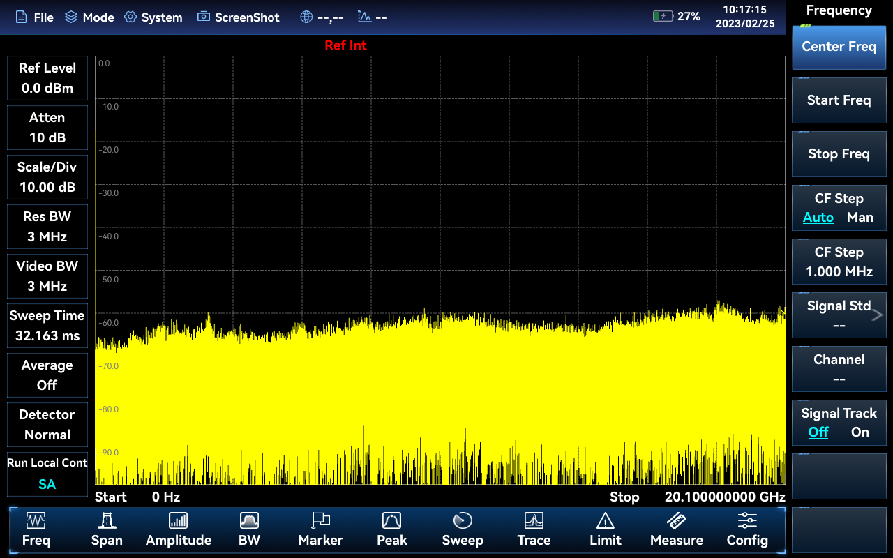
Spectrum Analyzer Mode
The Spectrum Analyzer function of the 4025 spectrum analyzer is equipped with Channel Power, Occupied Bandwidth, Adjacent Channel Power, Spectrum Emission Mask, Carrier-to-Noise Ratio, Audio Demodulation, Harmonic Distortion, Spectrum Emission Mask, Multi-Carrier Adjacent Channel Power and other test functions as standard, featuring high test sensitivity, fast sweeping speed, large dynamic range and good phase noise performance. 4025 spectrum analyzer has a variety of built-in predefined signal standards that can be called up directly, supports noise marker and frequency counter functions, can display 3 traces simultaneously, and has different detection methods such as Normal, Peak, Negative Peak, Sample, Average, RMS, and supports signal tracking and peak tracking functions.
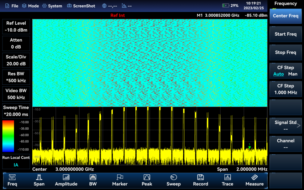
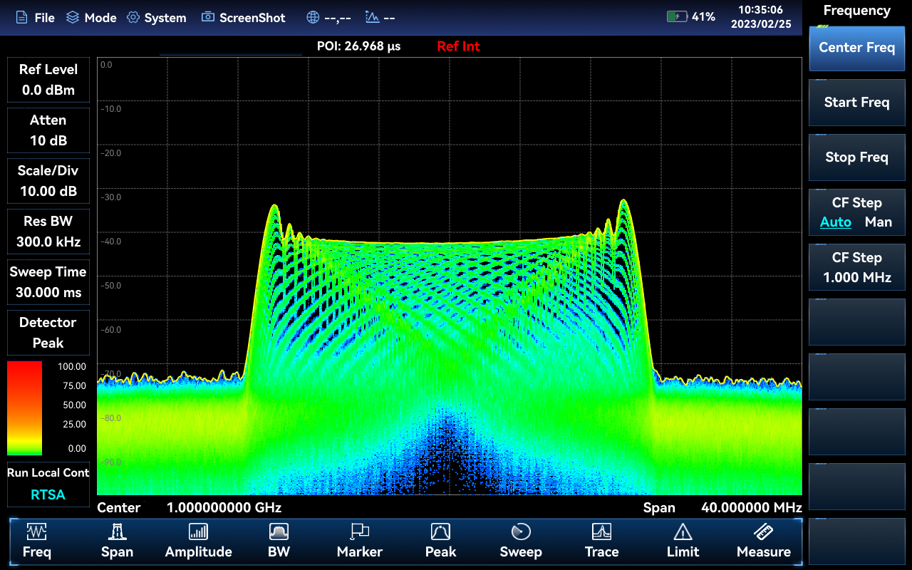
Interference Analyzer Mode (Option)
The Interference Analyzer option features spectrum measurement, Spectrogram and RSSI measurement. The Spectrogram uses a three-dimensional display of frequency-amplitude-time, making it easy to observe periodic or intermittent signals. The different colors in the Spectrogram show the strength of the signal amplitude, RSSI is mainly used to measure the power change of a point frequency signal in a time period, both Spectrogram and RSSI measurement support the automatic storage function of the signal.
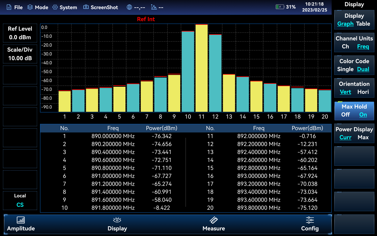
Channel Scanner Mode (Option)
The Channel Scanner Mode provides the measurement of the signal power of multiple channels. The signal power is displayed as a bar graph or as a table, and the signal power of up to 20 channels can be measured. There are three measurement modes depending on how the channels are set up: channel scanner, frequency scanner and list scanner, all of which allow the bandwidth and number of channels to be set.
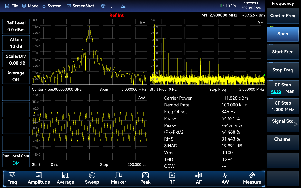
AM/FM/PM Analyzer Mode (Option)
The AM/FM/PM Analyzer mode provides the display of AM, FM and PM modulation signal profiles and the analysis of the associated parameters. The main plots and related parameters are measured as shown below.
RF spectrum: similar to the spectrum analyzer mode, the spectrum plot of the modulated Signal is displayed and the occupied bandwidth can be measured.
Audio Spectrum: displays the spectrum of the demodulated audio signal.
Audio Waveform: displays the waveform of the demodulated audio signal in the time domain.
Parameter analysis function: Carrier power, Demodulation rate, carrier frequency offset, modulation depth (AM), modulation frequency offset (FM), SINAD, modulation distortion, total harmonic distortion and other parameters of the modulated signal can be measured and analyzed.
USB CW Power Meter(Option)
The USB Power Meter can measure the CW signal power up to 40GHz with the external USB power sensor of 87230/87231/84232/87233 series.
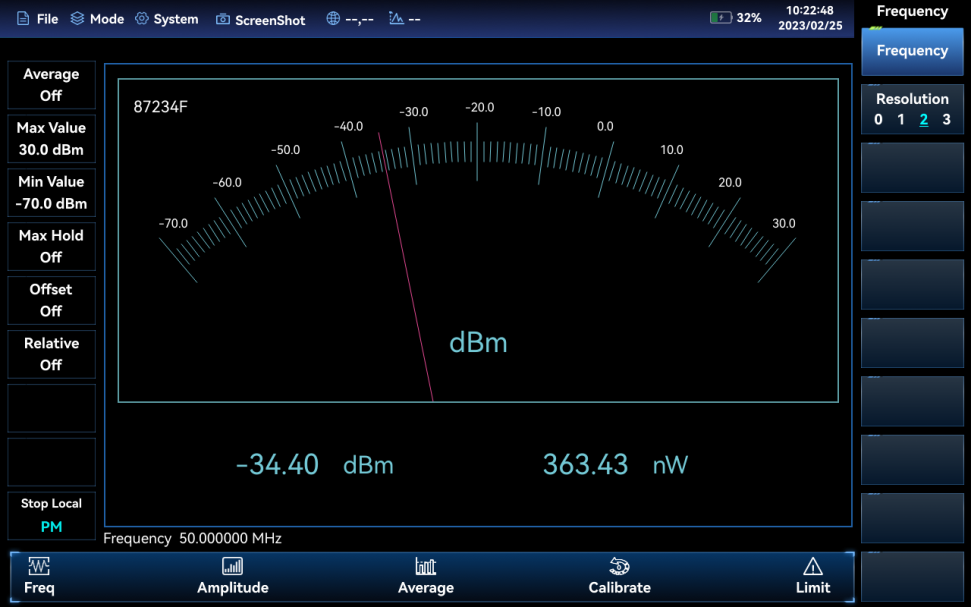
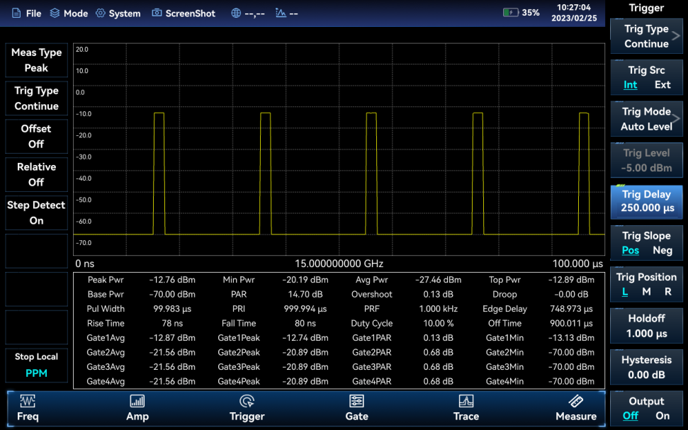
USB Peak Power Meter (Option)
4025 spectrum analyzer connects 87234D/E/F/L USB peak power sensor through a USB interface, which can test RF/microwave signals up to 67GHz, and realize pulse power measurement in a large dynamic range.
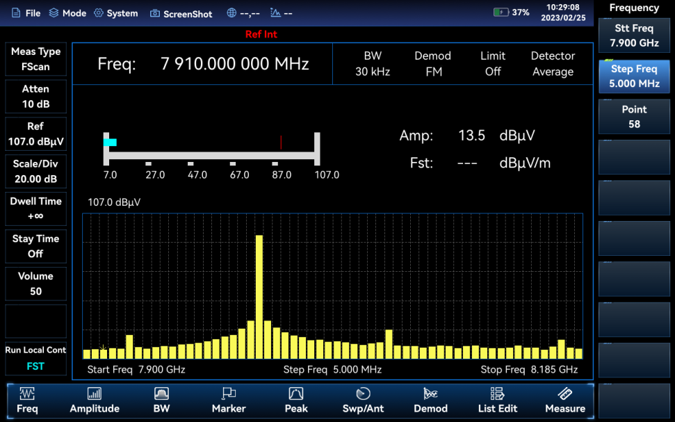
Field Strength Measurement (Option)
The 4025 spectrum analyzer can be used with portable antennas for field strength measurements and is widely used in space electromagnetic environment monitoring and radio management. The antenna file can be called up directly by the user or the antenna factor can be defined. Field Strength measurements can be made in three modes: point frequency measurements, frequency scan measurements and list scan measurements. Point frequency measurement is performed by setting the point frequency to observe the frequency offset, amplitude and field strength of the current signal; frequency scan measurement is performed by setting the start frequency, step frequency and number of scanning points to observe the amplitude and field strength of a frequency range; list scan measurement is performed by calling a pre-edited or saved list to observe the amplitude and field strength of the listed frequency points.
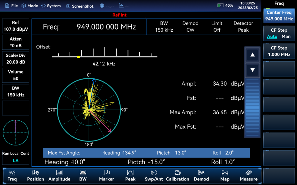
Location Analyzer Mode (Option)
The Location Analyzer option requires a directional antenna, USB electronic compass and GPS/Beidou options to achieve direct interference signal finding, horizontal scan direction finding and map cross-location. When equipped with the ZE9080 series antenna and handheld handle, a separate configuration is not necessary due to its built-in electronic compass.
Real-time Spectrum Analyzer Mode (Option)
The 4025 spectrum analyzer has a Real-time Spectrum analyzer function, which is mainly used for the capture and analysis of transient time-varying signals and burst signals. The real-time analysis bandwidth is up to 40MHz or 120MHz, and the transient signal DPX and Spectrogram measurement functions can be realized.
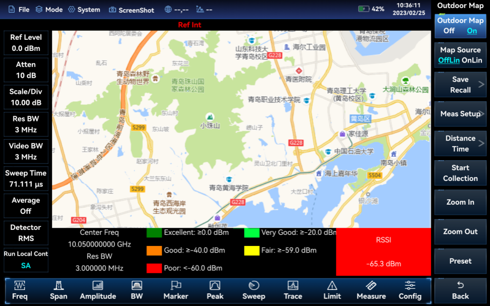
Out-door Map (Option)
The Outdoor Map option is a measurement function in Spectrum Analyzer mode that allows RSSI and Adjacent Channel Power Ratio tests to be performed and the test results can be marked on a map in real-time based on time or distance. The test results marked on the map can be saved to the instrument for subsequent recall.
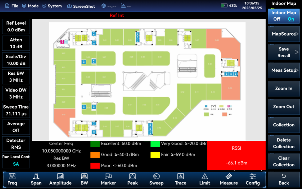
Indoor Map (Option)
The Indoor Map option allows RSSI and Adjacent Channel Power Ratio tests to be carried out. As the GPS signal cannot be received indoors, the user has to manually move the position and mark the test results on the map. The test results marked on the map can be saved to the instrument for later recall and viewing. A special software (included with the option) allows the user to convert the floor plan in image format into a tile map for storage on the instrument.
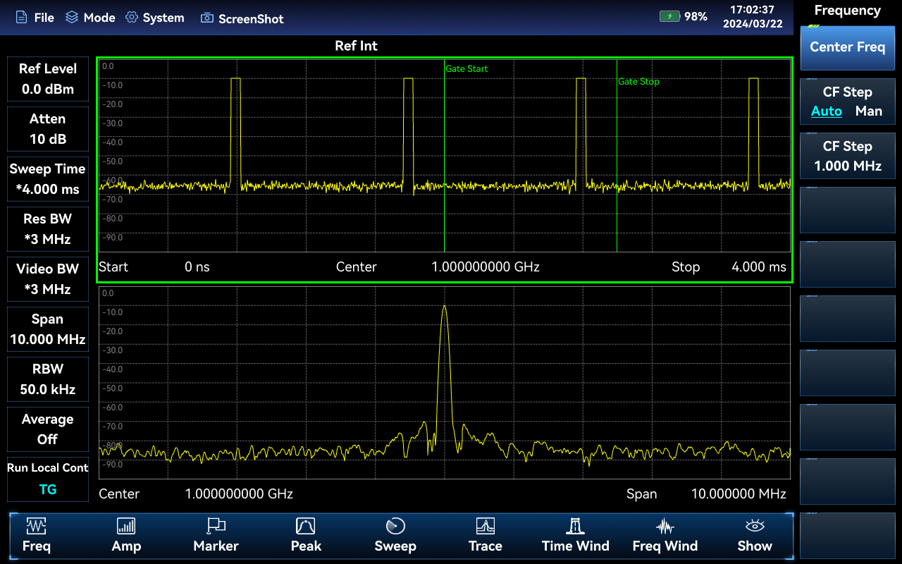
Time Gate Function(Option)
The Time Gate scanning function is used for interference detection of time-division signals, and the time gate scanning function is divided into the time domain window and the frequency domain window. In the time domain window, you can select the signals in a specific time period by setting the [Delay] and [Length], and the frequency domain results of the selected signals will be displayed in the frequency domain window. By setting [Delay] and [Length], the uplink signal can be selected out, so as to achieve the effect of "filtering" the downlink signal (the downlink signal will have an effect on the search of interfering signals).
![]() Typical Application
Typical Application
- Field comprehensive performance evaluation of electronic equipment
The 4025 spectrum analyzer has multiple advantages such as high-performance, fast sweeping speed, multiple test functions, easy operation, etc. With a handheld structure, small size, light weight, strong adaptability to the environment, and battery-powered, it can be applied to the field installation and commissioning of various electronic equipment such as radar, communications, electronic countermeasures and electronic reconnaissance, precision guidance and maintenance. - Field testing and diagnosis of transmitters and receivers
The 4025 spectrum analyzer has a variety of measurement function modes such as Spectrum Analyzer, Real-time Spectrum Analyzer, Interference Analyzer, AM/FM/PM Analyzer, Power Meter, Channel Scanner, Field Strength measurement, etc., and has a variety of intelligent measurement functions such as Channel Power, Occupied Bandwidth, Adjacent Channel Power Ratio, Carrier-to-Noise Ratio, Spurious Mask, Harmonic Distortion, etc., which can provide comprehensive spectrum analysis and diagnosis for field testing of transmitters and receivers. The new product is designed to provide comprehensive spectrum analysis and diagnostic services for transmitter and receiver field testing. - Broadband spectrum monitoring, interference identification
The 4025 spectrum analyzer can be used for electromagnetic environment detection, radio interference analysis, electromagnetic environment background assessment, spectrum monitoring and identification of illegal channel interference signals by means of external omnidirectional or directional antennas; it can be used for spectrum testing of complex signals such as time division multiple access signals and transient time-varying signals by means of Gated Sweep and Real-time Spectrum Analyzer.
![]() Specifications
Specifications
| del | 4025A: 9kHz~6GHz 4025B: 9kHz~9GHz 4025D: 9kHz~20GHz 4025E: 9kHz~26.5GHz 4025G: 9kHz~44GHz 4025K: 9kHz~54GHz |
| Frequency Reference Error | Frequency:10MHz Aging: ±5×10⁻⁷/year Initial Frequency Accuracy: ±3×10⁻⁷ Temperature Stability: ±1×10⁻⁷(-20℃ ~+55℃ , Comparative to 25℃ ±10℃ ) Frequency reference error: ± (last calibration date x aging rate + temperature stability + calibration accuracy) Note: default to the last calibration time is 1 year, the performance is guaranteed by the crystal manufacturer |
| Sweep Time | Range: 1μs~6000s(Zero Span) Accuracy: ±1.0%(Zero Span) |
| Frequency Readout Accuracy | ±(Frequency Readout× frequency Reference Error+1%× Span +10%× Resolution Bandwidth) |
| Frequency Span | Range: 0Hz(Zero Span),10Hz~ Upper limit of frequency range for corresponding models Accuracy: ±1.0% |
| Resolution Bandwidth | 1Hz~20MHz(1-2-3-5-8 steps) |
| Video Bandwidth | 1Hz~20MHz(1-2-3-5-8 steps) |
| SSB Phase Noise (1GHz Carrier,+15℃ ∼+35℃ ) | ≤-108dBc/Hz@10kHz, ≤-110dBc/Hz@100kHz ≤-118dBc/Hz@1MHz, ≤-129dBc/Hz@10MHz |
| Displayed Average Noise Level(input port is connected with a 50Ω load, 0dB input attenuation, average detector, the logarithm of video type, RBW normalized to 1Hz,+15℃ to +35℃ ) | 4025A/B/D Pre-amplifier ON: ≤-161dBm(2MHz~2.4GHz),≤-160dBm(2.4GHz~6GHz), ≤-159dBm(6GHz~9GHz), ≤-158dBm(9GHz~14GHz), ≤-156dBm(14GHz~20GHz) Pre-amplifier OFF: ≤-142dBm(2MHz~2.4GHz),≤-141dBm(2.4GHz~6GHz), ≤-140dBm(6GHz~9GHz), ≤-138dBm(9GHz~14GHz), ≤-138dBm(14GHz~20GHz) |
| 4025E/G/K Pre-amplifier ON: ≤-159dBm(2MHz~9GHz), ≤-156dBm(9GHz~14GHz) ≤-154dBm(14GHz~21GHz), ≤-154dBm(21GHz~32GHz) ≤-152dBm(32GHz~40GHz), ≤-148dBm(40GHz~44GHz) ≤-145dBm(44GHz~50GHz), ≤-140dBm(50GHz~54GHz) Pre-amplifier OFF: ≤-140dBm(2MHz~6GHz), ≤-138dBm(6GHz~9GHz) ≤-136dBm(9GHz~14GHz), ≤-136dBm(14GHz~21GHz) ≤-135dBm(21GHz~32GHz), ≤-133dBm(32GHz~40GHz), ≤-130dBm(40GHz~44GHz), ≤-126dBm(44GHz~50GHz), ≤-123dBm(50GHz~54GHz) | |
| Second Harmonic Distortion (0dB attenuation, -30dBm input signal, Pre-amplifier OFF) | ≤-70dBc(50MHz~27GHz) |
| TOI (-15dBm 2-tone signal input,100kHz span,0dB attenuator, Pre-amplifier OFF) | ≥+13dBm(50MHz~54GHz) |
| Image, multiple and out-of-band response (Mixer Level: -10dBm) | <-65dBc (10MHz~7.5GHz),<-60dBc (7.5GHz~10.5GHz), <-65dBc (10.5GHz~54GHz) |
| Residual Response (RF input:50 Ω load, input attenuation: 0dB) | Pre-amplifier ON: ≤-110dBm (10MHz~3GHz),≤-105dBm (3GHz~9GHz) ≤-103dBm (9GHz~12GHz),≤-100dBm (12GHz~20GHz) ≤-95dBm (20GHz~54GHz) Pre-amplifier OFF: ≤-90dBm (10MHz~20GHz) ≤-85dBm (20GHz~54GHz) |
| Reference Level | Range: -150dBm~+30dBm |
| Absolute Amplitude Accuracy(Attenuation: 10dB,-15dBm input power level, Pre-amplifier: OFF, RBW 1kHz) | 4025D ±1.30 dB (10MHz to 20GHz) |
| 4025A/B/E/G/K: ±1.00 dB (10MHz~20GHz) ±1.40 dB (20GHz~44GHz) ±1.80 dB (44GHz~54GHz) | |
| Input Attenuator | Attenuation range: 0~30dB,2dB steps |
| Maximum Input Power | 4025A/B/D:+27dBm CW Power(input frequency ≥50MHz) 4025E/G/K:+25dBm CW Power(input frequency ≥50MHz) |
| Display | Logarithmic Scale: 0.1~10dB/div, minimum 0.1dB step (10 division display) Scale Unit: V, A, W, dBm, dBW, dBV, dBmV, dBμV, dBA, dBmA, dBμA |
| Detector Type | Normal, Peak, Negative peak, Sample, Average, RMS |
| Dimensions | 316.5mm(W)×236.5mm(H)×75mm(D) (Without side strap and interface plug, the back bracket is closed) 316.5mm(W)×236.5mm(H)×68mm(D) (Without side strap、 interface plug and back bracket) |
| Weight | 4025A/B/D: Typical: 3.0kg (without internal battery),3.5kg (with internal battery) 4025E/G/K: Typical: 3.3kg (without internal battery),3.8kg (with internal battery) |
| Working Temperature | -20℃ ~+55℃ (Battery discharge: -20℃ ~+55℃ , Battery charge: +10℃ ~+45℃ ) |
| Storage Temperature | -50℃ ~+70℃ (Storage temperature of the battery: -20℃ ~+50℃ ,Storage time:<1 month) |
| Electromagnetic Compatibility | Conforms to the relevant requirements of item 3.9.1 of GJB3947A-2009 |
| Power Input Requirement | AC power adapter: input voltage: 100 to 240VAC,50/60Hz Output voltage: 19VDC,4.7A Built-in Lithium-ion rechargeable battery: Nominal voltage: 10.8V |
| Power Consumption | 4025A/B/D: Typical: 22W~28W (Spectrum Analyzer mode,default state) 4025E/G/K: Typical: 26W~33W (Spectrum Analyzer mode,default state) |
| Battery Operating Time | 4025A/B/D: Typical: 4h (Spectrum Analyzer mode,default state) 4025E/G/K: Typical: 3h (Spectrum Analyzer mode,default state) |
| Test Interface | 4025A/B/D RF input: N(F) connector 4025E RF input: 3.5mm(M) connector 4025G/K RF input: 2.4mm(M) connector |
| Other Interfaces | 10MHz reference input/output: SMA(f) External trigger input: SMA(f) GPS antenna: SMA(f)(option) IF output: SMA(f)(option) Wi-Fi/4G antenna: SMA(f)(option, The input interface of 4G antenna is reserved and not supported for now.) |
| Communication and Auxiliary Interfaces | USB interface: 2 USB3.0 A-type interface 1 USB2.0 Type C-type interface 1 USB3.0 B-type interface(reserved) LAN interface: standard RJ-45 type Audio phone interface: standard 3.5mm SD/SIM card: Micro SD card and SIM card slot(The 4G option is reserved) |
![]() Host Model
Host Model
| Numbering | Name | Describe |
| 4025K | Spectrum Analyzer | 9kHz~54GHz |
| 4025G | Spectrum Analyzer | 9kHz~44GHz |
| 4025E | Spectrum Analyzer | 9kHz~26.5GHz |
| 4025D | Spectrum Analyzer | 9kHz~20GHz |
| 4025B | Spectrum Analyzer | 9kHz~9GHz |
| 4025A | Spectrum Analyzer | 9kHz~6GHz |
![]() Option Model
Option Model
| Numbering | Name | Describe | Optional |
| 4025-01 | Optional Accessories of English Version | English Signs, Menu | |
| 4025-03 | User Manual (English) | User Manual English Version | |
| 4025-05 | Programming Manual (English) | Programming Manual English Version | |
| 4025-S01 | USB CW Power Meter Option | CW Power measurement function available with external USB continuous wave power sensor 87230/87231/87232/87233. | |
| 4025-S02 | USB Peak Power Meter Option | Peak power measurement is available and requires the 87234D/E/F/L USB peak/average power sensor to be used. | |
| 4025-S03 | Interference Analyzer Option | Provides spectrogram, RSSI measurements and more | |
| 4025-S04 | Channel Scanner Option | To Realize Signal Power Measurement of Multiple Channels and Frequency | |
| 4025-S05 | Field Strength Option | For measuring the radiation intensity of the electric field of the device under test. | |
| 4025-S06 | Outdoor Map Option | RSSI and Adjacent Channel Power Ratio tests can be carried out under the indoor map, with the results marked on the map by dotting the correlation between signal strength and color. | |
| 4025-S07 | Indoor Map Option | RSSI test and Adjacent Channel Power Ratio test can be done under the outdoor interference map, and the test results can be marked on the map in real time according to time or distance, to be used with the 4025-H01 option. | |
| 4025-S08 | AM/FM/PM Analyzer Option | Realize AM, FM and PM modulation signal analysis and measurement function. | |
| 4025-S09 | Zero Span IF Output | Output IF signal at zero span | |
| 4025-S10 | Gated Sweep Option | Used for time division interference signal testing | |
| 4025-S11 | Location Analyzer Option | For locating external sources of interference or unknown signals, to be used in conjunction with the 4025-H01 option, the USB electronic compass option and the directional antenna option. | |
| 4025-S12 | 40MHz Bandwidth Real-time Spectrum Analyzer Option | Provide 40 MHz bandwidth Real-time Spectrum analysis function | |
| 4025-S13 | List Sweep Option | Realize continuous sweep of multiple frequency bands | |
| 4025-S14 | IQ Analyzer Option | Realization of IQ data capture and display function | |
| 4025-S15 | GSM/EDGE Measurement Option | 2G GSM/EDGE demodulation analysis with 4025-H37X option | |
| 4025-S16 | LTE Analyzer Option | Demodulation analysis of 4G LTE FDD/TDD signals with 4025-H37X option | |
| 4025-S17 | 5G NR Option | Demodulation of 5G NR signals can be analyzed with 4025-H37X option | |
| 4025-S18 | Vector signal Analysis function option | Built-in software function,used for demodulating and analyzing various sing-carrier digital modulated signals. | |
| 4025-S19 | EMI analysis function option | Built-in software function providing EMI scanning , list scanning functions, with CISPR average,CISPR effective and quasipeak detector | |
| 4025-S20 | Phase Noise Meter function option | Built-in software function providing.single sideband phase noise curve and single-point phase noise testing | |
| 4025-H01 | GPS/Beidou Location | GPS or Beidou positioning function can be realized through the external antenna. | |
| 4025-H02 | Wi-Fi Communication Option | Wireless communication with external devices. | |
| 4025-H03 | Aluminium alloy transit case with wheels and handle | Tie rod aluminium alloy box | |
| 4025-H04 | Transit case with wheels and handle | Pull-rod transport box | |
| 4025-H05 | Backpack | Portable Backpack | |
| 4025-H06 | Power Adapter | Power Adapter | |
| 4025-H07 | 9900mAh Lithium-ion Rechargeable Battery | Standby battery pack, nominal voltage 10.8V, battery capacity 9900mAh, not suitable for air transport carry-on. | |
| 4025-H08 | 9000mAh Lithium-ion Rechargeable Battery | Standby battery pack, nominal voltage 10.8V, battery capacity 9000mAh, suitable for air transport carry-on. | |
| 4025-H09 | Vehicle Power Adaptor | Car charger with input voltage 12~24V and output voltage 19V for powering handheld measuring instruments. | |
| 4025-H10 | Smart Battery Charging Base | Lithium-ion battery charging stand | |
| 4025-H11 | Micro SD Card | Micro SD card, capacity: 128G. | |
| 4025-H12 | 87230 USB CW Power Sensor | Frequency range: 9kHz~6GHz, Interface: N(m). | |
| 4025-H13 | 87231 USB CW Power Sensor | Frequency range: 10MHz~18GHz, Interface: N(m). | |
| 4025-H14 | 87232 USB CW Power Sensor | Frequency range: 50MHz~26.5GHz, Interface: 3.5mm(m). | |
| 4025-H15 | 87233 USB CW Power Sensor | Frequency range: 50MHz~40GHz, Interface: 2.4mm(m). | |
| 4025-H16 | 87234D USB Peak/ CW Power Sensor | Frequency range: 50MHz~18GHz, Interface: N(m). | |
| 4025-H17 | 87234E USB Peak/ CW Power Sensor | Frequency range: 50MHz~26.5GHz, Interface: 3.5mm(m). | |
| 4025-H18 | 87234F USB Peak/ CW Power Sensor | Frequency range: 50MHz~40GHz, Interface: 2.4mm(m). | |
| 4025-H19 | 87234L USB Peak/ CW Power Sensor | Frequency range: 500MHz~67GHz, Interface: 1.85mm(m). | |
| 4025-H20 | ZE9080 Directional Antenna A | Frequency range: 9kHz~20MHz, Interface: N(f).Recommended for use with H24. | |
| 4025-H21 | ZE9080 Directional Antenna B | Frequency range: 20MHz~200MHz, Interface: N(f).Recommended for use with H24. | |
| 4025-H22 | ZE9080 Directional Antenna C | Frequency range: 200MHz~500MHz, Interface: N(f).Recommended for use with H24. | |
| 4025-H23 | ZE9080 Directional Antenna D | Frequency range: 500MHz~8GHz, Interface: N(f).Recommended for use with H24. | |
| 4025-H24 | ZE9080 Antenna Amplifier | Frequency range: : 9kHz~8GHz,N(f),can be used with the ZE9080 Antenna Module A/B/C/D option, Internal with amplifier and electronic compass. | |
| 4025-H25 | ZE9080 Antenna Transport Case | Transport case for ZE9080 antenna, to hold ZE9080 Antenna Module A/B/C/D and ZE9080 handheld module. | |
| 4025-H26 | 700MHz~6GHz Directional Antenna | Active Log-periodic Antenna, Frequency: 700MHz~6GHz, Interface: SMA(f). | |
| 4025-H27 | 680MHz~10GHz Directional Antenna | Active Log-periodic Antenna, Frequency: 680MHz~10GHz, Interface: SMA(f). | |
| 4025-H28 | 680MHz~20GHz Directional Antenna | Active Log-periodic Antenna, Frequency: 680MHz~20GHz, Interface: SMA(f). | |
| 4025-H29 | 6GHz Omni-directional Antenna | Portable Omni-directional Antenna, Frequency: 680MHz~6GHz, Interface: SMA(m). | |
| 4025-H30 | 8GHz Omni-directional Antenna | Portable Omni-directional antenna, Frequency: 300MHz~8GHz, Interface: SMA(m). | |
| 4025-H31 | 700MHz~6GHz Passive Directional Antenna | Passive Log-periodic Antenna, Frequency: 700MHz~6GHz, Interface: SMA(f). | |
| 4025-H32 | 680MHz~10GHz Passive Directional Antenna | Passive Log-periodic Antenna , Frequency: 680MHz~10GHz, Interface: SMA(f) | |
| 4025-H33 | 680MHz~18GHz Passive Directional Antenna | Passive Log-periodic Antenna, Frequency: 680MHz~18GHz, Interface: SMA(f). | |
| 4025-H34 | USB Electronic Compass | External USB Electronic Compass can be used with 4025-H26~4025-H28, 4025-S11 options. | |
| 4025-H35 | N/SMA-JJ RF Cable(2m) | N/SMA (M-M) RF coaxial cable, DC~18GHz,length: 2m | |
| 4025-H36 | PBS1 Near-field Probe | Maximum frequency: 9 GHz, with 1 electric field probe and One magnetic field probe for 6mm, 12mm, 25mm and 50mm, Interface: SMB(m). | |
| 4025-H37A | 120MHz Bandwidth Real-time Spectrum Analysis Option | 120MHz bandwidth real-time spectrum analysis option for 4025A only. | |
| 4025-H37B | 120MHz Bandwidth Real-time Spectrum Analysis Option | 120MHz bandwidth real-time spectrum analysis option for 4025B only. | |
| 4025-H37D | 120MHz Bandwidth Real-time Spectrum Analysis Option | 120MHz bandwidth real-time spectrum analysis option for 4025 only. | |
| 4025-H37E | 120MHz Bandwidth Real-time Spectrum Analysis Option | 120MHz bandwidth real-time spectrum analysis option for 4025E only. | |
| 4025-H37G | 120MHz Bandwidth Real-time Spectrum Analysis Option | 120MHz bandwidth real-time spectrum analysis option for 4025G only. | |
| 4025-H37K | 120MHz Bandwidth Real-time Spectrum Analysis Option | 120MHz bandwidth real-time spectrum analysis option for 4025K only. | |
| 4025-H38 | Handheld Directional Antenna | Passive Log-Periodic Antenna,Frequency Range 380MHz~20GHz,with build-in Electronic Compass and RF Test Cable(Connector Type:N Type Male) | |
| 4025-H39 | Handheld High-Gain Directional Antenna | Horn Antenna,Frequency Range 18GHz~40GHz,with build-in Electronic Compass and RF Test Cable(Connector Type:2.92mm Male) | |
| 4025A-JL | Calibration Service | Provides metrological calibration services, provides metrological reports, applies to 4025A only. | |
| 4025B-JL | Calibration Service | Provides metrological calibration services, provides metrological reports, applies to 4025B only. | |
| 4025D-JL | Calibration Service | Provides metrological calibration services, provides metrological reports, applies to 4025D only. | |
| 4025E-JL | Calibration Service | Provides metrological calibration services, provides metrological reports, applies to 4025E only. | |
| 4025G-JL | Calibration Service | Provides metrological calibration services, provides metrological reports, applies to 4025G only. | |
| 4025K-JL | Calibration Service | Provides metrological calibration services, provides metrological reports, applies to 4025K only. | |
| 4025A-EWT1 | Extended Warranty-1 year | Extended 1-year out of standard warranty, 2 optional for 2-year extended warranties, and so on, service does not include calibration, one-way shipping only | |
| 4025B-EWT1 | Extended Warranty-1 year | Extended 1-year out of standard warranty, 2 optional for 2-year extended warranties, and so on, service does not include calibration, one-way shipping only | |
| 4025D-EWT1 | Extended Warranty-1 year | Extended 1-year out of standard warranty, 2 optional for 2-year extended warranties, and so on, service does not include calibration, one-way shipping only | |
| 4025E-EWT1 | Extended Warranty-1 year | Extended 1-year out of standard warranty, 2 optional for 2-year extended warranties, and so on, service does not include calibration, one-way shipping only | |
| 4025G-EWT1 | Extended Warranty-1 year | Extended 1-year out of standard warranty, 2 optional for 2-year extended warranties, and so on, service does not include calibration, one-way shipping only | |
| 4025K-EWT1 | Extended Warranty-1 year | Extended 1-year out of standard warranty, 2 optional for 2-year extended warranties, and so on, service does not include calibration, one-way shipping only |
![]() Standard accessories
Standard accessories
| Numbering | Name | Describe | Optional |
| 3 | Product certificate | Certificate of Conformity | |
| 2 | Product quick user guide | Quick start using the instrument | |
| 1 | Power line assembly | Standard 3-Phase Power Cord Power adapter:100~240V 50/60Hz input, 19V,4.7A output Lithium-ion rechargeable battery |

