
1435 Series Signal Generator
SKU : 1435 Series Signal Generator
Short Description
- Frequency range
9kHz to 40GHz
- RF Modulation Bandwidth
2GHz
- SSB phase noise(10GHz carrier@10kHz offset)
-113dBc/Hz
- Maximum output power
+20dBm at full frequency band
![]() Product Overview
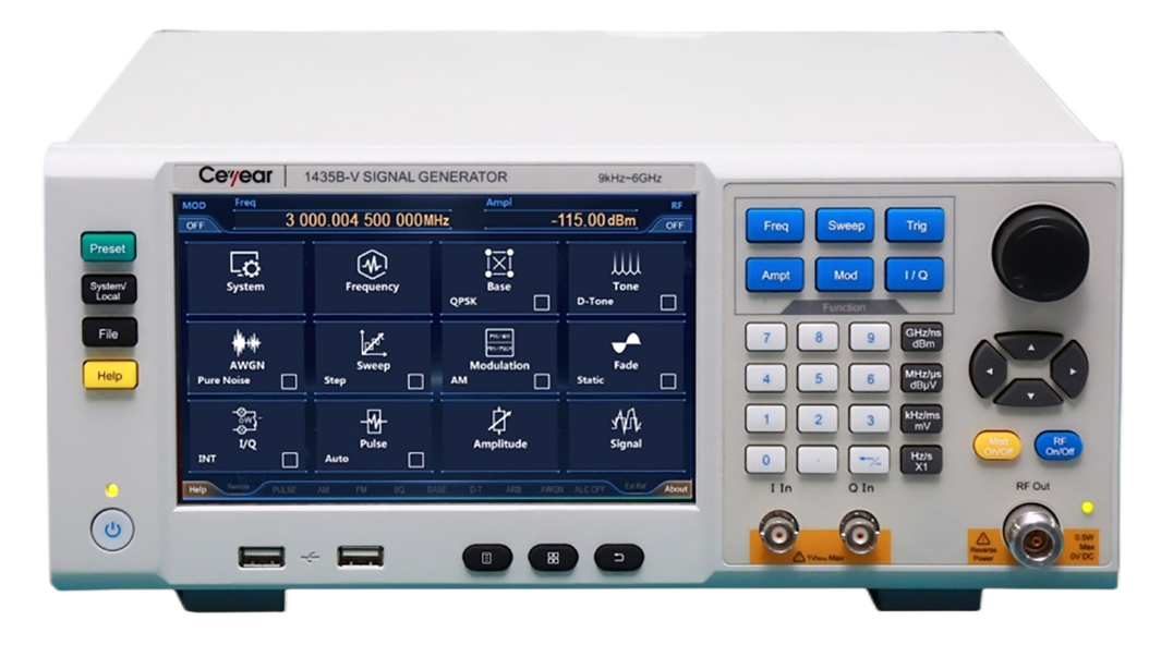
Product Overview
Based on innovative technologies, the 1435 series signal generator achieves balance in terms of performance, economy and volumetric weight. It also has excellent spectral purity, with a single side band (SSB) phase noise of -136dBc/Hz (when the carrier is 1GHz and the frequency offset is 10kHz) or -116dBc/Hz (when the carrier is 10GHz and the frequency offset is 10kHz). It provides a high power output and a large dynamic range, with the maximum output power up to 20dBm@20GHz and an output power dynamic range greater than 150dB. It responds fast and switches to another frequency in only 1ms, which shortens the test time and improves test efficiency, meeting the needs of massive data testing; in addition, it also has excellent analog modulation and pulse modulation functions. By adopting advanced frequency synthesis and RF channel signal processing technologies, it can achieve high performance while reducing the cost. Besides, it is equipped with a 7-inch high-sensitivity LED touch screen, and supports operation by touch screen, panel buttons, rotary knobs, external mouse and keyboard, etc., which fully upgrades the users’ operation experience. It adopts portable 3U chassis structure and is featured by small size and light weight, and thus is easy to carry. The 1435 series signal generator can meet both the test requirements for high performance in the R&D phase and the test requirements for high efficiency in the production phase.
![]() Features
Features
- Wide frequency range
- High output power
When the H08 high-power output option is selected, the measured value of the full-band output power of the 1435A/B/C/D series signal generator can be above 20dBm and the full-band output power of the 1435F series signal generator can be above 17dBm. In the test where high-power excitation signals are required, the 1435 series signal generator can be used to obtain the required test signal without an external amplifier.
![]() Typical Application
Typical Application
- The 1435 series signal generator provides complete functions and a frequency range of 9kHz~40GHz. It provides AM, FM, ΦM, and PM analog modulation functions and supports step scan and list scan. Also, it has excellent performance. By adopting a design which realizes the balance between performance, economy and volumetric weight, it supports free configuration of various options, which makes it widely available. In respect of cost, it can be used for teaching; in respect of performance, it can be used in laboratory tests.
- The 1435 series signal generator supports high-performance pulse modulation, with a pulse-to-modulation switch ratio greater than 80dB, the rise and fall time less than 10ns, and the minimum pulse width of 20ns. It supports various pulse patterns such as pri stagger, prf jittering and pulse string, which is suitable for radar system testing. It has excellent phase noise performance and is available for receiver testing. It has a small size and can be carried along for field testing.
- The 1435 series signal generator takes only 1ms to switch to another frequency. It provides a high test speed, shortens the test time, and improves the test efficiency, thus meeting the requirements of massive data test. It provides a high power output and needs no external power amplifier, thus saving the space and cost. It supports multiple control interfaces such as USB, LAN and GPIB, which facilitates the formation of an automated test system and is suitable for production line test.
![]() specifications
specifications
Technical Specifications
| Frequency Features | |||||
| FrequencyRange | 1435A:9kHz~3GHz 1435B:9kHz~6GHz 1435C:9kHz~12GHz 1435D:9kHz~20GHz 1435F:9kHz~40GHz | Frequency | N (number of internal harmonic waves) | ||
| 9kHz≤f<250MHz | 1/8 | ||||
| 250MHz≤f≤375MHz | 1/16 | ||||
| 375MHz<f≤750MHz | 1/8 | ||||
| 750MHz<f≤1.5GHz | 1/4 | ||||
| 1.5GHz<f≤3GHz | 1/2 | ||||
| 3GHz<f≤6GHz | 1 | ||||
| 6GHz<f≤12GHz | 2 | ||||
| 12GHz<f≤24GHz | 4 | ||||
| 24GHz<f≤40GHz | 8 | ||||
| Frequency Resolution | 0.001Hz | ||||
| Frequency Switching Time | ≤1ms (typical value 2) | ||||
| Time Base Aging Rate (Typical Value) | Standard: ±5×10⁻⁷/year (after continuous switch-on for 30 days) High Stability Time Base option H10: ±5×10⁻⁸/year (after continuous switch-on for 30 days) ±5×10⁻¹⁰/day(after continuous switch-on for 30 days) | ||||
| ReferenceOutput | Frequency | 10MHz | |||
| Power | >+4dBm, to 50Ω load | ||||
| Reference Input | Frequency | 1MHz~50MHz, step 1Hz | |||
| Power | 0dBm~+7dBm, impedance 50Ω | ||||
| Scanning Features | |||||
| Scanning Mode | Step Scan, List Scan | ||||
| Scan Dwell Time | 100μs~100s | ||||
| Power Features | |||||
| Minimum Power | Standard | Option H01 | |||
| -15dBm (can be set -20dBm) | -110dBm (can be set -135dBm) | ||||
| Maximum Power(25±10°C) | Frequency Range | Standard | High Power Output Option H08 | ||
| 1435A/B | |||||
| 9kHz≤f≤3GHz | 18dBm | 22dBm | |||
| 3GHz<f≤5GHz | 16dBm | 20dBm | |||
| 5GHz<f≤6GHz | 15dBm | 18dBm | |||
| 1435C/D | |||||
| 9kHz≤f≤3GHz | 16dBm | 21dBm | |||
| 3GHz<f≤20GHz | 15dBm | 20dBm | |||
| 1435F | |||||
| 9kHz≤f≤3GHz | 14dBm | 20dBm | |||
| 3GHz<f≤17GHz | 13dBm | 17dBm | |||
| 17GHz<f≤40GHz | 11dBm | 15dBm | |||
| Standard | |||||
| Power Accuracy(25±10°C) | Power (dBm) Frequency | 10~Maximum Power | -10 to 10 | -15 to 10 | |
| 9kHz≤f≤2GHz | ±0.8dB | ±0.6dB | ±1.5dB | ||
| 2GHz<f≤20GHz | ±0.9dB | ±0.7dB | ±1.5dB | ||
| 20GHz<f≤40GHz | ±0.9dB | ±0.8dB | ±1.8dB | ||
| H01A/B Programmable Step Attenuator Option | |||||
| Power (dBm) Frequency | 10 to Maximum Power | -10 to 10 | -70 to 10 | -90 to 70 | |
| 9kHz<f≤2GHz | ±0.8dB | ±0.6dB | ±0.7dB | ±1.4dB | |
| 2GHz<f≤20GHz | ±0.9dB | ±0.7dB | ±0.7dB | ±1.6dB | |
| 20GHz<f≤40GHz | ±0.9dB | ±0.8dB | ±1.1dB | ±2.0dB | |
| Power Resolution | 0.01dB | ||||
| Output Impedance | 50Ω (rated value3) | ||||
| Source Standing Wave Ratio, VSWR (Internal Fixed Amplitude) (Typical Value) | 9kHz≤f≤3GHz | <1.7 | |||
| 3GHz<f≤13GHz | <1.6 | ||||
| 13GHz<f≤20GHz | <1.8 | ||||
| 20GHz<f≤40GHz | <1.6 | ||||
| Maximum Reverse Power | 0.5W (0V DC) (rated value) | ||||
| Spectral Purity 4 | |||||
| Harmonic Wave(at +10dBm) | 9kHz≤f≤10MHz | <-23dBc | |||
| 10MHz<f≤2GHz | <-30dBc | ||||
| 2GHz<f≤6GHz (1435B) | <-30dBc | ||||
| 2GHz<f≤20GHz | <-55dBc | ||||
| 20GHz<f≤40GHz | <-50dBc (typical value) | ||||
| SubharmonicWave (at +10dBm) | 9kHz≤f≤6GHz | None | |||
| 6GHz<f≤12GHz | <-60dBc | ||||
| 12GHz<f≤24GHz | <-55dBc | ||||
| 24GHz<f≤40GHz | <-50dBc | ||||
| Non-HarmonicWave (at 0dBm,10kHz Frequency Offset) | Frequency | Standard | Low Phase Noise Option | ||
| 9kHz≤f≤250MHz | <-54dBc | <-60dBc | |||
| 250MHz<f≤3GHz | <-62dBc | <-77dBc | |||
| 3GHz<f≤6GHz | <-56dBc | <-71dBc | |||
| 6GHz<f≤12GHz | <-50dBc | <-65dBc | |||
| 12GHz<f≤24GHz | <-44dBc | <-59dBc | |||
| 24GHz<f≤40GHz | <-38dBc | <-53dBc | |||
| SSB Phase Noise (dBc/Hz at +10dBm) | Standard | ||||
| Frequency | 100Hz | 10kHz | |||
| 100MHz | -83 | -115 | |||
| 250 MHz | -93 | -127 | |||
| 500MHz | -89 | -121 | |||
| 1 GHz | -83 | -115 | |||
| 2 GHz | -77 | -109 | |||
| 3GHz | -74 | -105 | |||
| 4 GHz | -71 | -103 | |||
| 6 GHz | -68 | -99 | |||
| 10 GHz | -63 | -95 | |||
| 20 GHz | -57 | -89 | |||
| 40 GHz | -51 | -83 | |||
| Low Phase Noise Option | |||||
| Frequency | 100Hz | 1kHz | 10kHz | 100kHz | |
| 100MHz | -83 | -112 | -131 | -131 | |
| 250 MHz | -93 | -123 | -139 | -139 | |
| 500MHz | -89 | -119 | -135 | -135 | |
| 1 GHz | -83 | -113 | -132 | -132 | |
| 2 GHz | -77 | -107 | -126 | -126 | |
| 3GHz | -74 | -104 | -121 | -121 | |
| 4 GHz | -71 | -101 | -120 | -120 | |
| 6 GHz | -68 | -98 | -115 | -115 | |
| 10 GHz | -63 | -93 | -113 | -113 | |
| 20 GHz | -57 | -87 | -107 | -107 | |
| 40 GHz | -51 | -81 | -101 | -101 | |
| Modulation Features | ||
| FrequencyModulation5(Option H02) | Maximum frequency offset: N × 16MHz (N is the number of fundamental harmonic wave)Accuracy (1kHz modulation rate, frequency offset: N × 500kHz): ± (2% × set frequency offset + 20Hz) | |
| Modulation rate (3dB bandwidth, frequency offset: N × 500kHz): DC-7MHzDistortion (1kHz rate, frequency offset: N × 500kHz): <0.4% | ||
| Phase Modulation5 (Option H02) | Maximum phase offset: N × 16rad (N is the number of fundamental harmonic wave) Accuracy (1kHz modulation rate, frequency offset: N × 500kHz): ± (2% × set phase offset + 0.01rad)Modulation rate (3dB bandwidth, phase offset: N × 8rad): DC-1MHzDistortion (1kHz modulation rate, phase offset: N × 8rad): <0.4% | |
| Amplitude Modulation5 (Option H02) | Maximum depth: >90%Modulation rate: (1kHz modulation rate, 30% modulation depth): ± (4% × set depth+1%)Modulation rate (bandwidth: 3dB; modulation depth: 30%; frequency test points:1GHz, 5GHz, 20GHz, 40GHz): DC~100kHzDistortion: (1kHz modulation rate, linear mode, total harmonic distortion, 30%modulation depth): <2%; | |
| PulseModulation 6(Option H03) | Switching ratio | >80dB |
| Rise and fall time | <10ns | |
| Minimum pulse of internal fixed amplitude | 1μs | |
| Minimum pulse of non-fixed amplitude | 100ns | |
Narrow Pulse Modulation 6 (Option H04) | Switching ratio | >80dB |
| Rise and fall time | <10ns | |
| Minimum pulse of internal fixed amplitude | 1μs | |
| Minimum pulse of non-fixed amplitude | 20ns | |
| Internal Analog Modulation Signal Generator (Option H02) | It provides three independent signals for frequency/phase modulation, amplitude modulation and low frequency output signalsWaveform: sine wave, square wave, triangle wave, sawtooth waveFrequency range: sine wave 0.1Hz~10MHzSquare wave, triangle wave, sawtooth wave 0.1Hz~1MHzFrequency resolution: 0.1HzLow frequency output: amplitude 0~5V peak (rated value), to 50Ω load | |
| Internal Pulse Generator (Option H03) | Pulse width: 20ns~(42s-10ns) (rated value) Pulse period: 40ns~42s (rated value) Resolution: 10ns |
| Multi-Function Function Generator (Option H05) | The Multi-function generator consists of 7 waveform generators. The generator can be set separately or five generators can be set simultaneously by using the AM, FM/ΦM and the composite modulation features in the low-frequency output. Waveform: Function generator 1: sine wave, triangle wave, square wave, sawtooth wave, pulse Function generator 2: sine wave, triangle wave, square wave, sawtooth wave, pulse Dual function generator: sine wave, triangle wave, square wave, sawtooth wave, pulse, phase offset and amplitude ratio of audio 2 relative to audio 1; Scan function generator: sine wave, triangle wave, square wave, sawtooth wave; Noise generator 1: uniform, Gaussian; Noise generator 2: uniform, Gaussian; DC: LF output only; Frequency parameters: Sine wave: 0.1Hz to 10MHz; Triangle wave, square wave, sawtooth wave, pulse: 0.1Hz to 1MHz; Resolution: 0.1Hz; |
| General Features | |
| RF Output Port | 1435A/B/C: N type (negative), impedance 50Ω 1435D: 3.5mm (positive), N type (negative) (option H91), impedance 50Ω 1435F: 2.4mm (positive), impedance 50Ω |
| Maximum Dimensions (width × height × depth) | Width × height × depth: 330mm × 147mm × 397mm (excluding the handle) 420mm × 147mm × 445mm (including the handle) |
| Weight | <12kg (the weight varies with the model and option configuration) |
| Power Supply | 100~120VAC, 50~60Hz; or 200~240VAC, 50~60Hz (self-adaptive) |
| Power Consumption | Less than 300W |
| Temperature Range | Operating temperature: 0°C~+50°C; storage temperature: -40°C~+70°C |
Note:
1. The 1435 series signal generator can be stored at ambient temperature for 2 hours. After preheating for 30 minutes, the attenuator is automatically coupled (or ALC power is greater than -5dBm) to meet the performance of each indicator within a given working range.
2. The typical value is a supplementary feature given based on the stereotype value, which is only for user reference, and will not be assessed.
3. The rated value refers to the expected performance, or describes the product performance that is useful in the product but is not included in the product warranty.
4. The spectral purity indicates that the point frequency has no modulation mode.
5. The technical specifications of frequency modulation, phase modulation and amplitude modulation are applicable to frequencies above 10MHz.
6. The technical specifications of pulse modulation and narrow pulse modulation are applicable to frequencies above 50MHz.

