
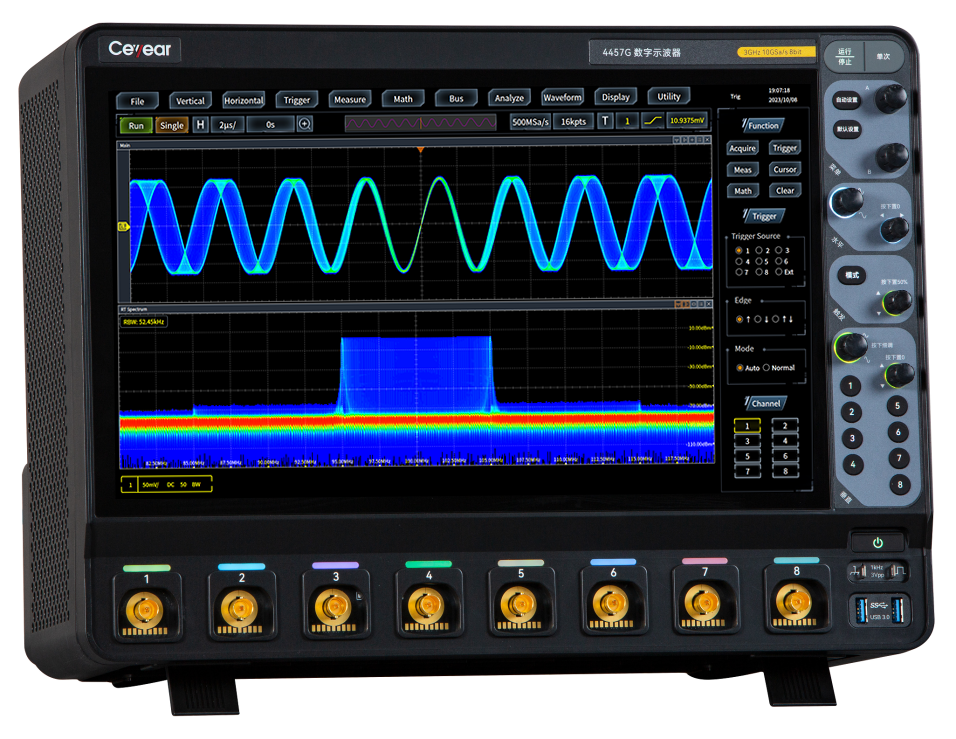
4457 Series Digital Oscilloscope
SKU : 4457 Series Digital Oscilloscope
![]() Product Overview
Product Overview
The 4457 series digital oscilloscope has 4 product models, with bandwidth ranging from 1GHz to 4GHz, sampling rates of 10GSa/s and 20GSa/s, vertical resolution of 8-bit, storage depth of 2Gpts, and a fastest waveform capture rate of 1.2 million waveforms per second. The innovative Any Acquire technology provides users with a brand new oscilloscope experience.
![]() Features
Features
Main Features
● Multi in one instrument
Oscilloscope, logic analyzer, function generator, bus analyzer, real-time spectrum analyzer, and digital voltmeter are all in one, providing more testing functions to help you easily tackle various challenges.
● Any Acquire Technology
The unique arbitrary capture technology provides you with higher sampling rates, faster waveform capture rates, more dazzling displays, deeper storage, more accurate digital triggering, and more comprehensive analysis.
● Rich probe options
Supports passive probes, high-voltage single ended probes, high-voltage differential probes, current probes, and active probes to meet your probe testing needs in different situations.
● High definition touch integrated LCD screen
15.6-inch high-definition LCD display with a resolution of up to 1920 × 1080. Capacitive touch screen, supporting single point and multi-point touch, enabling quick operation of waveforms and menus.
● Portable structure, rich peripheral interfaces
Portable structure, 8U standard rack installation, rich peripheral interfaces, maximum weight 15kg.
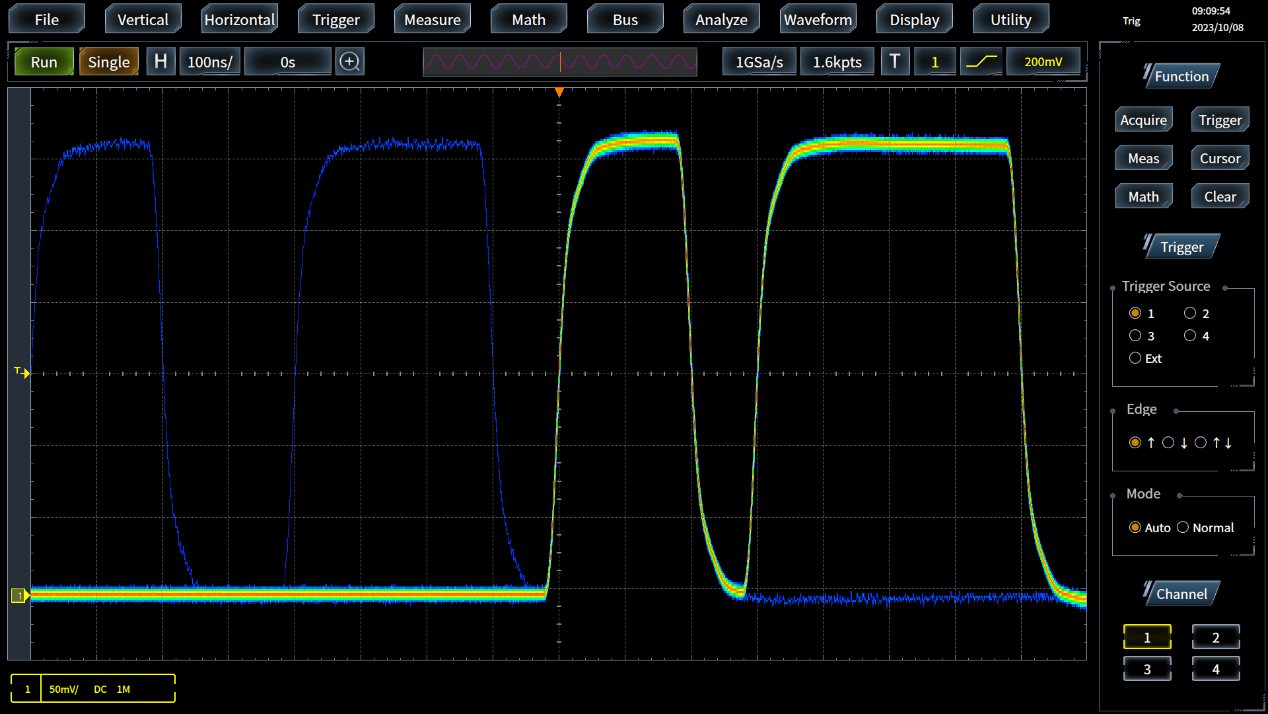
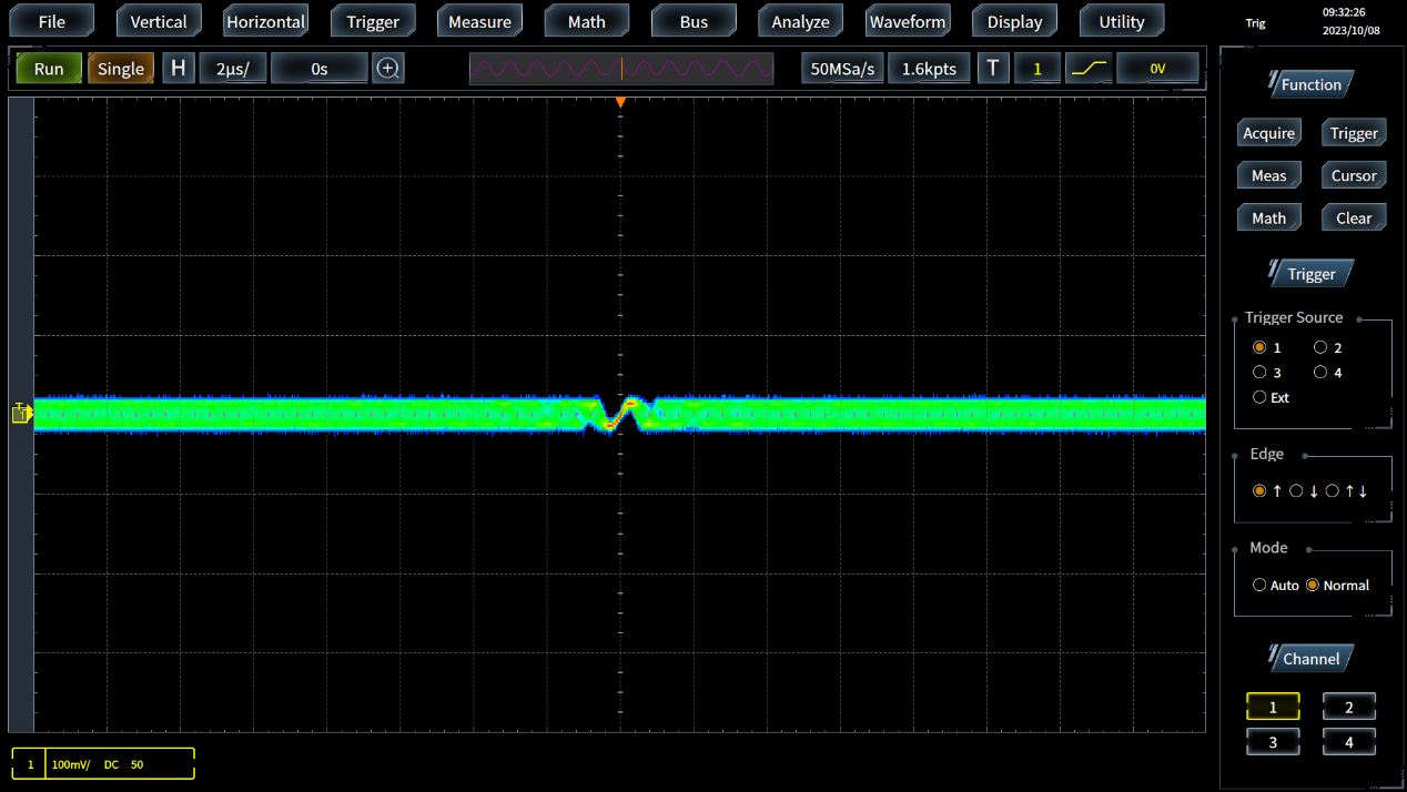
With a waveform capture rate of up to 1.2 million waveforms per second and a sampling rate of 20GSa/s, it can quickly detect and capture occasional events.
The oscilloscope has a waveform capture rate of up to 1.2 million waveforms per second and a sampling rate of 20GSa/s, greatly increasing the probability of capturing glitches and occasional events, allowing you to see more waveform details in a longer acquisition time.
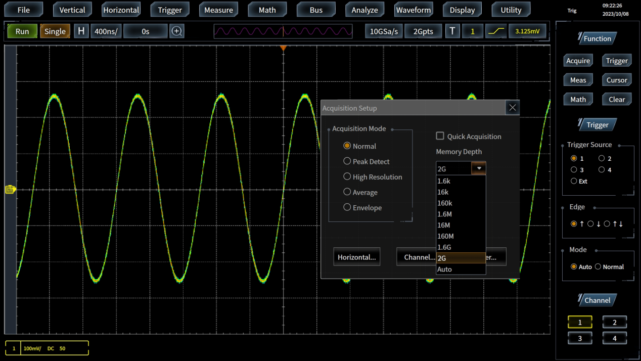
Up to 2Gpts of deep storage, maintaining longer recording time, segmented storage, more effectively capturing and storing important signals.
2Gpts of deep memory allows the oscilloscope to maintain a high sampling rate and fast waveform capture rate even in slow timing mode. Full hardware window extension, which can zoom in and observe the details of the waveform locally, providing you with synchronized display of the global and detailed waveform.
The 4457 series oscilloscope comes standard with segmented memory acquisition, which can maintain fast response speed and screen update rate even when the oscilloscope operates in deep storage mode.
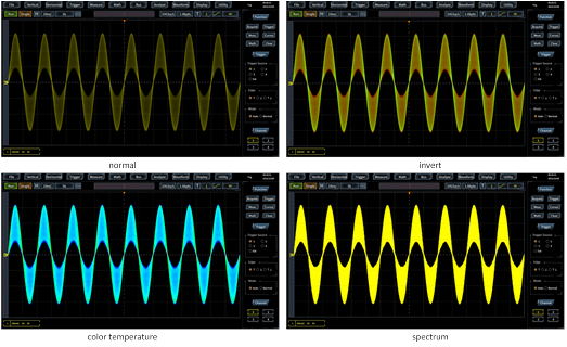
256 levels of grayscale and four waveform colors display, providing an extraordinary visual experience.
The 4457 series oscilloscope adopts digital fluorescence 3D display technology, which represents the probability of event occurrence through the brightness or temperature of colors, and provides four waveform colors including normal, inverse, color temperature, and spectrum, enhancing the ability to view occasional events.
Rich triggering functions, precise digital triggering, and accurate locking of triggering events.
The 4457 series oscilloscope provides a rich set of triggering functions, including edge, edge jump, dual edge time, dual edge event, glitch, pulse width, short pulse, timeout, code type, status, establish hold, window, area trigger (visual trigger), etc., to quickly lock in the events of interest in the complex sampling information.
The 4457 series oscilloscope adopts precise digital triggering technology to directly measure the trigger point of ADC collected samples, which can suppress the influence of interference signals, quickly lock the trigger event, and lay the foundation for accurate display and analysis of signals on the oscilloscope. The sensitivity of digital triggering is up to 0.1 grid.
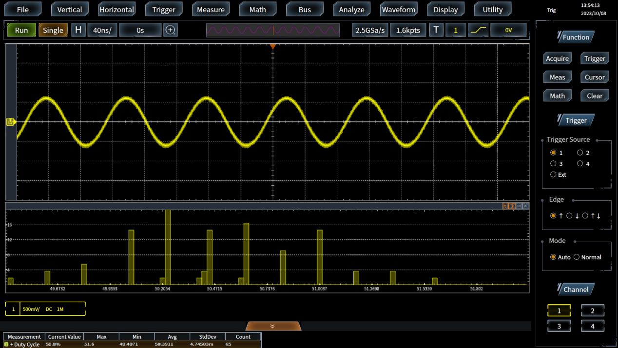
Powerful computational analysis tools provide you with in-depth data mining and analysis.
The 4457 series oscilloscope provides a comprehensive set of analysis tools, including waveform based and screen based cursor, mathematical operations, hardware parameter measurement, FFT analysis, histogram statistics, etc., to provide you with in-depth data mining and analysis, thus meeting your multi-dimensional measurement and analysis needs.
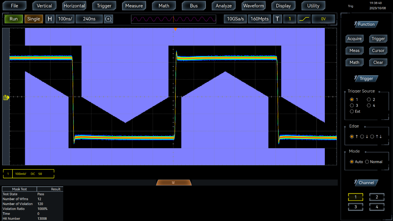
Rich waveform recording and playback, extreme templates, power measurement, and Bode plot analysis functions.
The 4457 series oscilloscope provides rich waveform recording and playback, extreme templates, power measurement, and Bode plot analysis functions, providing you with powerful data analysis capabilities to fully meet your measurement and analysis needs.
The waveform recording and playback function is used for real-time recording of waveforms and playback to view waveform details; Extreme template testing has built-in standard templates, and users can also customize templates for passing tests; The power measurement function can be used for testing power quality, switch losses, harmonics, ripples, safe working areas, etc; Baud plot analysis detects the frequency response of the control loop and analyzes the stability of the feedback system.
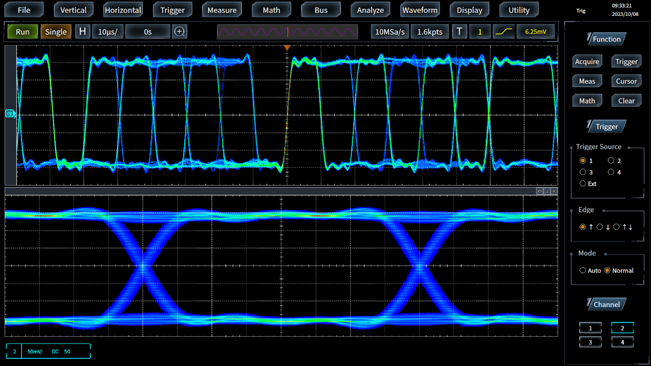
Powerful eye diagram and shake analysis function, capable of measuring eye diagram parameters and conducting in-depth shake analysis.
The 4457 oscilloscope has powerful eye diagram and jitter analysis functions, which can quickly overlay and display eye diagrams for all captured UI and measure eye diagram parameters. Simultaneously conducting in-depth jitter analysis, displaying histograms, spectrograms, and trend graphs of time interval error (TIE), decomposing jitter to calculate the magnitude of its components, and drawing bathtub curves.
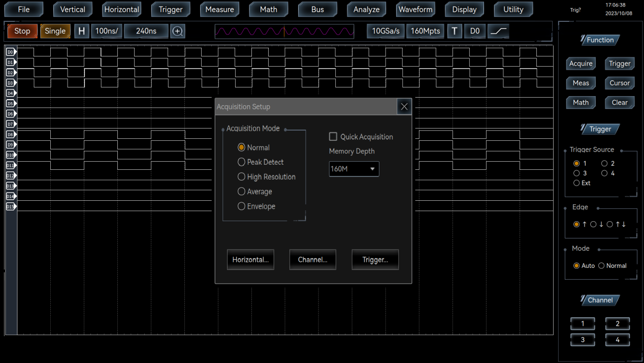
Integrate 16 channel logic analyzer function to quickly solve problems in the design and analysis of mixed signal systems.
The logic analyzer option can provide a timing sampling rate of 2.5GSa/s and a maximum time resolution of 400ps for all digital channels, which can more accurately reflect the timing relationship of the measured signal. A maximum depth storage of 160Mpts enables the logic analyzer to maintain a high sampling rate even when capturing long-term records.
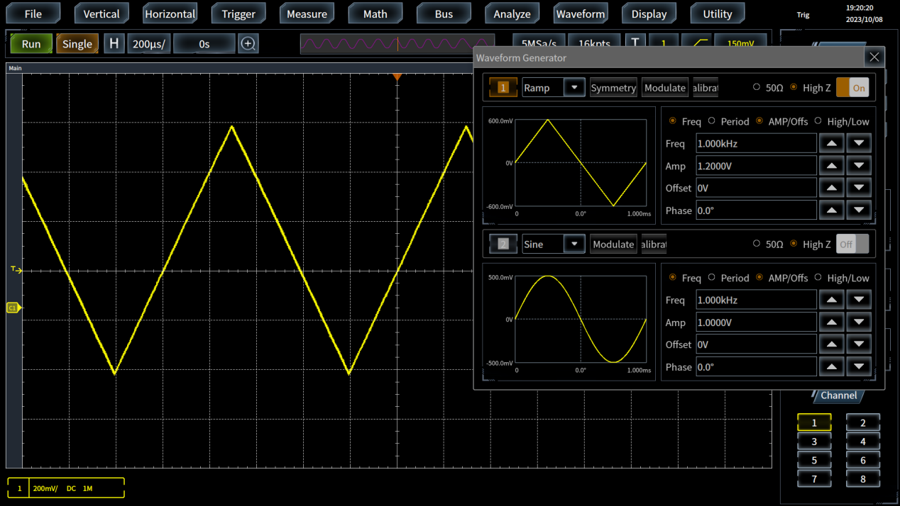
2-channel function generator function, supporting various waveforms such as sine wave, square wave, pulse, arbitrary wave, etc. It also supports modulation waveform output such as FM, AM, FSK, etc.
The function generator has 2 output channels, which can help you simulate sensor signals or add noise to signals for margin testing in your design.
The function generator provides sine waveform output up to 50MHz, including square wave, ramp wave, pulse, DC, noise, arbitrary wave, etc SinX/X、 Exponential rise/fall, Gaussian, Lorentz curves, semi vector curves, electrocardiograms, and other waveforms. In addition, it supports the output of modulated waveforms such as FM, AM, and FSK. The arbitrary waveform output function with a recording length of 64k points can be used to edit and modify the output waveform through the capacitive touch screen, thus quickly generating the waveform you need.
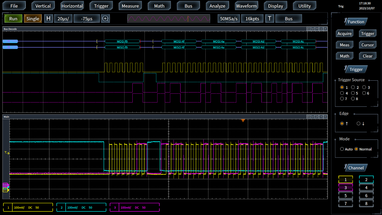
Full hardware decoding and analysis supporting multiple buses.
Bus analyzer supports I2C、SPI 、CAN、LIN、FlexRay、RS232、USB、Audio、MIL-STD-1553、ARINC429 By automatically triggering and analyzing various buses, we provide testing solutions for serial buses such as embedded, automotive, computer, and audio systems. Based on FPGA full hardware decoding technology, we have powerful serial bus triggering and analysis capabilities, enhancing the probability of capturing occasional serial communication errors.
In addition to providing traditional digital views, it also offers higher-level bus view displays and can view captured bus packets in the form of event tables with time stamps.
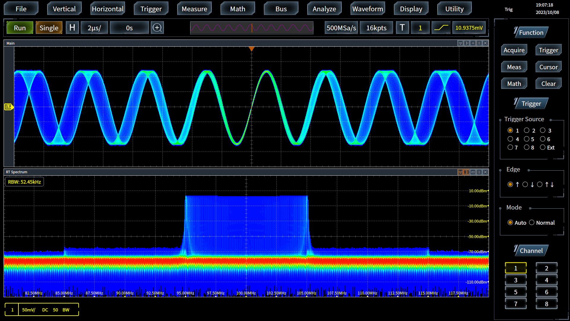
Full hardware real-time spectrum analyzer function.
Full hardware architecture real-time spectrum analyzer function, with a maximum frequency range up to oscilloscope bandwidth. Real time analysis bandwidth options include 10MHz, 20MHz, 40MHz, 80MHz, 160MHz, and 320MHz. By using stacked FFT and digital fluorescence display technology, the FFT refresh rate is greater than 400000 times per second, greatly improving the probability of capturing narrow pulses or transient signals and enhancing the ability to view occasional events.
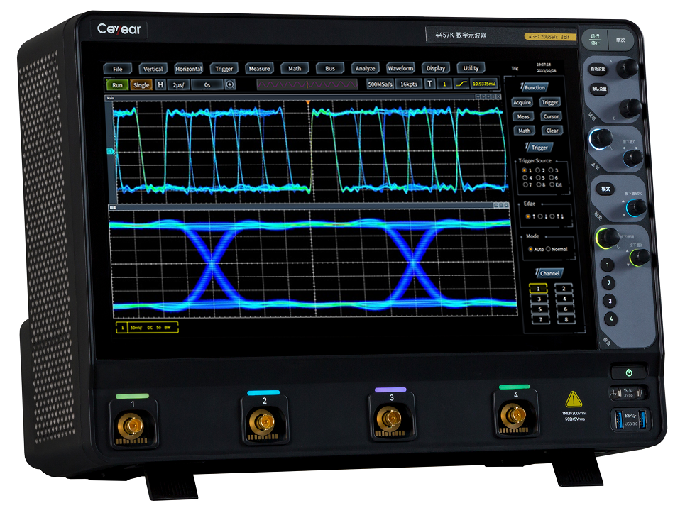
15.6-inch brand new capacitive touch screen, beautiful view, convenient and easy to use.
15.6-inch capacitive touch screen, supporting single point and multi-point touch, quickly realizing waveform scaling and movement, thoughtful design, super strong experience; Multi window free setting, beautiful view, conducive to observation; Speech recognition, more intelligent operation.
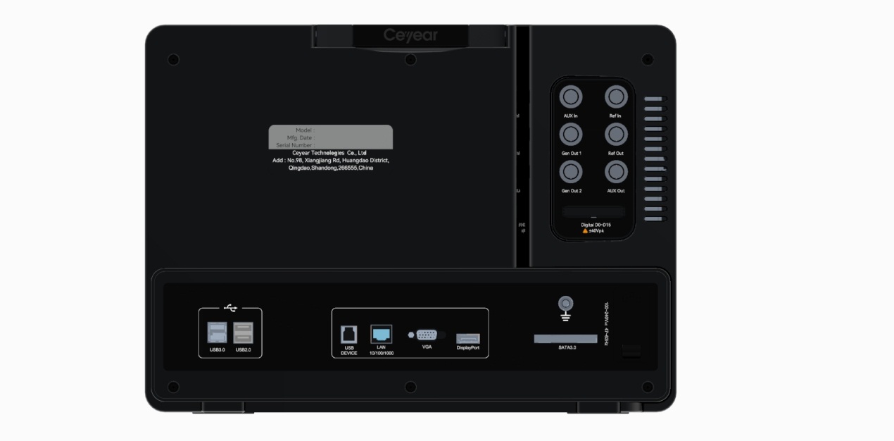
Standard 8U rack, rich peripheral interfaces, powerful connectivity.
Standard 8U rack installation, providing rich peripheral interfaces, can be easily connected to the network through Ethernet ports, realizing remote network control, facilitating function expansion and system construction.
![]() Typical Application
Typical Application
● The 4457 series digital oscilloscope is a multifunctional comprehensive testing instrument that integrates an oscilloscope, logic analyzer, function generator, real-time spectrum analyzer, bus analyzer, and digital voltmeter. It is a universal debugging and verification tool that can help you quickly identify, locate, analyze, and solve problems. It is widely used in analog and digital circuit design and debugging, circuit diagnosis and transient signal capture, power device and power electronics design, embedded design and debugging, automotive electronics testing, product testing and quality control, education and training, and other fields.
![]() specifications
specifications
| Model Indicator | 4457E | 4457F | 4457G | 4457K | |
| Vertical system | Number of channels | 4, 8 (optional) | 4 | ||
| Bandwidth (≥10mV/div, 50Ω) | 1GHz | 2GHz | 3GHz | 4GHz | |
| Bandwidth (≥10mV/div, 1MΩ) | 500MHz | 500MHz | 500MHz | 500MHz | |
| Rising time (50Ω) | ≤450ps | ≤225ps | ≤150ps | ≤113ps | |
| Bandwidth limit | 20MHz, 500MHz, 1GHz, 2GHz, full bandwidth (Note: | ||||
| bandwidth limiting scale does not exceed the bandwidth of each model) | |||||
| Input impedance | E/F/G:50Ω±2%, 1MΩ±1%//24pF±3pF | ||||
| K:50Ω±2%, 1MΩ±1% | |||||
| Input coupling | 50Ω:DC | ||||
| 1MΩ: DC, AC | |||||
| Vertical sensitivity range | 50Ω: 1mV/div~1V/div | ||||
| 1MΩ: 1mV/div~10V/div | |||||
| Vertical gain accuracy | ±3% (Note: ≥ 10mV/div), ±5% (Note: <10mV/div) | ||||
| Vertical resolution | 8bit | ||||
| Dynamic range | ±4 divisions from the center of the screen | ||||
| Maximum input voltage | 50Ω:5Vrms | ||||
| 1MΩ:300Vrms | |||||
| Offset range | 50Ω: ±0.5V (1mV/div~10mV/div), ±1V (20mV/div~100mV/div), ±4V (200mV/div~1V/div) | ||||
1MΩ: ±0.5 V (1mV/div~10mV/div), ±1V (20mV/div~100mV/div) | |||||
| Isolation between channels | ≥30 dB | ||||
| Level | Maximum sampling rate | E/F/G: 10GSa/s (full channel) | |||
K: 20GSa/s (full channel) | |||||
| Max. memory depth | 2Gpts (full channel) | ||||
| Acquisition mode | Normal: Acquisition and sampling values | ||||
Peak: sampling glitch is 100ps at least | |||||
High resolution: Vertical resolution increase to reduce noise | |||||
Envelope: Minimum and maximum envelope responds to peak data on multiple acquisitions | |||||
Average: average contains 2-512 waveforms | |||||
Scroll: Scroll the waveform from right to left on the screen, with time base 100ms/div~1000s/div | |||||
Segmentation: Standard capture memory is divided into up to 262,144 segments | |||||
| Fastest waveform capture rate | Fast sampling mode: 1,200,000 waveforms/second | ||||
Segmented mode: 450,000 waveforms/second | |||||
| Time base range | 10ps/div~1000s/div | ||||
| Time base accuracy | ± (1ppm+1ppm/year aging rate) | ||||
| Time base delay range | 1 screen before trigger, maximum 5000s after trigger | ||||
| Inter-channel delay adjustment range | ±150ns, step 100ps | ||||
| Trigger | Trigger source | Analog channels CH1~CH4, external, digital channels D0~D15 (optional H01), analog channels CH5~CH8 (optional eight-channel option) | |||
| Trigger mode | Auto, normal, single | ||||
| Trigger holdoff range | 6.4ns to 200s | ||||
| Trigger level range | Internal: ±4 divisions | ||||
External: ±0.4V, external/10: ±4V | |||||
| Trigger sensitivity | Internal: user adjustable, 0.1 division step | ||||
External: 50mV, external/10: 500mV | |||||
| Trigger type | Edge: Trigger on the rising edge, falling edge, or any edge of any channel or auxiliary input | ||||
| Edge transition: Trigger when a rising or falling edge spanning two voltage levels is encountered within or outside a specified period of time | |||||
| glitch: Specify the glitch width (less than the narrowest pulse width) and slope to trigger when a glitch is encountered | |||||
| Pulse width: Trigger on positive or negative pulse width at >, <, = or ≠ specific time period; pulse width range: 6.4ns~12.8s; resolution 1.6ns | |||||
| Short pulse: trigger when the pulse exceeds one threshold but fails to exceed another threshold | |||||
| Timeout: trigger when the event stays high, low, or high-low for a specified period of time | |||||
| Code pattern/status: Identify the trigger condition by looking up the specified code pattern or code pattern and edge (status) on the input channel | |||||
| Video trigger: trigger on line, odd field, even field, or full field of NTSC, PAL, and SECAM signals | |||||
| Edge-to-edge: Prepare on a selected edge on any channel and wait for a specified time or event to trigger on another selected edge, including dual edge times and dual edge events | |||||
| Build and hold: trigger in case of a violation of the build time or hold time between clock and data present on any channel | |||||
| Window: trigger acquisition when an event enters, leaves, or holds within or outside a window determined by two user-adjustable thresholds. Events can be limited by time or logic value | |||||
| Burst pulse: trigger on the Nth edge of a burst pulse that occurs after a certain amount of idle time | |||||
| Cascade: "B" event is triggered after "A" event has been triggered N times or for a certain period of time. The "A" and "B" events do not support video trigger and bus trigger. | |||||
| Measurement and analysis system | Auto Meas | There are 42 types, but up to 20 types can be displayed on the screen. The include period, frequency, delay, top fluctuation, rising time, falling time, positive duty cycle, negative duty cycle, positive pulse width, negative pulse width, burst width, burst interval, burst period, phase, positive overshoot, negative overshoot, peak-to-peak, amplitude, high level, low level, maximum, minimum, mean, cycle mean, root mean square, cycle mean square, number of positive pulses, number of negative pulses, number of rising edges, number of falling edges, area, cycle area, pulse top, pulse bottom, pulse amplitude, crosspoint voltage, specified voltage time, top, middle, bottom, maximum time, and minimum time. | |||
| Cursor | Waveform and screen | ||||
| Measurement statistics | Mean value, minimum, maximum, standard deviation | ||||
| Ref Level | User-definable reference level for automatic measurements, which can be specified as a percentage or in units | ||||
| Range | Selectable screen or waveform cursor | ||||
| Waveform histogram | The waveform histogram provides a data value indicating the total number of hits within the user-defined area of the display screen | ||||
| Signal source: CH1~CH4 | |||||
| Type: vertical, horizontal | |||||
| Measurement types: 12 types, including number of waveforms, number of hits in the box, number of peak hits, median, maximum, minimum, peak-to-peak, mean value, standard deviation, Sigma1, Sigma2, Sigma3 | |||||
| Waveform math | Supported math functions at one time: 27 Math functions: add, subtract, multiply, divide, absolute value, square, square root, exponential (natural number base, 10 base), logarithmic (natural number base, 10 base), mean, maximum, minimum, envelope, interpolation, comparison, inverse, reverse, integral, sum of square roots, differential, FFT, XY | ||||
| Filter: high-pass filter, low-pass filter, smoothing filter | |||||
| FFT: Vertical scale is set to linear RMS or dBm, dBmV; window is set to rectangular, Hamming, Hanning, Blackman-Harris | |||||
| Limit and template test(Option S01) | Select template: standard, customized, limit test | ||||
| Test source: CH1~CH4 | |||||
| Template ratio: lock to source ON, lock to source OFF | |||||
| Test stop conditions: no stop, waveform (1~1,000,000), time (1 second~48 hours) | |||||
| Failure action: stop acquisition, save waveform, save screen, auxiliary output | |||||
| Result display: display results, display detailed results | |||||
| Power measurement and analysis(Option S02) | Supported measurement types: 5 | ||||
| Measurement types: power quality, ripple, harmonics, ON/OFF loss, safe operating area | |||||
| Baud chart analysis(Option S03) | It is necessary to procure H02 function generator option | ||||
| Detect the frequency response of the control loop, analyze the stability of the feedback system | |||||
| Eye diagram analysis(Option S20) | Eye diagram display | ||||
| Eye diagram measurement: mainly including eye height, eye width, 0 level, 1 level, Q factor, etc. | |||||
| Jitter analysis(Option S21) | Jitter display: histogram, trend graph, spectrogram, bathtub curve. | ||||
| Jitter decomposition: Tj, Rj, Dj, Pj, DDj, ISI, DCD | |||||
| Real-time spectrum analyzer | Real-time spectrum analyzer(Option S22) | Number of analyzing channels: 1 | |||
| Analysis frequency range: DC ~ oscilloscope bandwidth | |||||
| Real-time analysis bandwidth: 10 MHz, 20 MHz, 40 MHz, 80 MHz, 160 MHz and 320 MHz | |||||
| Window type: rectangular window, Hanning window, Hamming window, black-man window, flat-top window, triangular window, Kessel window | |||||
| FFT waveform refresh rate: >400,000 times/sec | |||||
| Bus analyzer | Decoding channel | 1 | |||
| Display Format | Binary, hexadecimal | ||||
| Display mode | Bus view, digital view, event table with timescale information | ||||
| I2C trigger and analysis option S04 | Trigger on Start, Repeat Start, Stop, Acknowledge Loss, Address, Data, Address/Data on I2C bus up to 10 Mbps, support 7-bit/10-bit address protocol type | ||||
| RS232 trigger and analysis option S05 | Trigger on transmit bit start, transmit data, Tx parity error, transmit packet end, receive bit start, receive data, Rx parity error, receive packet end within 50bps to 2Mbps. | ||||
| SPI trigger and analysis option S06 | Trigger on SS valid, MOSI, MISO, MOSI and MISO on SPI bus within 10Mbps rate | ||||
| CAN trigger and analysis option S07 | Trigger on frame start, frame end, bit fill error, response error, ID, data, ID and data, frame type on CAN signals within 10kbps to 1Mbps | ||||
| LIN trigger and analysis option S08 | Trigger on synchronization, identifier, data, identifier/data, wake-up frame, sleep frame and error on LIN signals up to 800bps to 100kbps; protocol standard supported: V1.0, V2.0 | ||||
| FlexRay trigger and analysis option S09 | Trigger on frame header, indicator bit, identifier, loop count, header field, data, identifier and data, end of frame, and error within 2.5Mbps, 5Mbps and 10Mbps | ||||
| Audio trigger and analysis option S10 | Trigger on word select, data within 10Mbps; protocol types supported: I2S, LJ, RJ, TDM | ||||
| USB trigger and analysis option S11 | Trigger on synchronization, reset, abort, resume, end-of-packet, token packet, data packet, handshake packet, special packet, and error on USB signals at low speed 1.5Mbps or full speed 12Mbps | ||||
| MIL-STD-1553 trigger and analysis option S12 | Trigger on synchronization, command, status, data, time, parity error, synchronization error, manchester error, discontinuity error on MIL-STD-1553 signal at 1Mbps. | ||||
| ARINC429 trigger and analysis module option S13 | Trigger on word start, word stop, tab, tab+ bits, tab range, error, all 0 bits, all 1 bits, all bits (eye) of ARINC 429 bus signals within 1 Mbps rate | ||||
Logic analyzer . Min lysis . Option H01 | Number of digital channels | 16 | |||
| Threshold selection | TTL (1.4V), 5VCMOS (2.5V), 3.3VCMOS (1.65V), 2.5VCMOS (1.25V), ECL (-1.3V), PECL (3.7V), user defined | ||||
| Custom threshold range | ±20V in 10mV increments | ||||
| Threshold accuracy | ±(150mV + 3% of threshold settings) | ||||
| Maximum input voltage | ±40V peak | ||||
| Input dynamic range | ±10V relative to threshold | ||||
| Minimum voltage swing | 500mVpp | ||||
| Maximum input switching rate | 400MHz | ||||
| Input impedance | 100kΩ±2% | ||||
| Vertical resolution | 1bit | ||||
| Timed sampling rate | 2.5GSa/s | ||||
| Memory depth | 160Mpts | ||||
| Minimum detection pulse width | 2ns | ||||
| Function generator . . . . Option H02 | Number of channels | 2 | |||
| Max. output frequency | 50MHz | ||||
| Maximum sampling rate | 200MSa/s | ||||
| Vertical resolution | 14bit | ||||
| Output impedance | 50Ω (typical value), high impedance | ||||
| Output waveform | Standard waveforms: sine wave, square wave, ramp, pulse, DC, noise, and arbitrary waves | ||||
| Built-in waveforms: SinX/X, exponential up-and-down, Gaussian, Lorentz curve, semi-positive curve, electrocardiogram | |||||
| Modulation | FM, AM, FSK | ||||
| Sine wave | Frequency range: 0.1Hz~50MHz | ||||
| Harmonic distortion: -40dBc (>200mVpp @50Ω, 1kHz) | |||||
| Spurious: -40dBc (>200mVpp @50Ω, 1kHz) | |||||
| Total harmonic distortion: 1% (>200mVpp @50Ω, 1kHz) | |||||
| Signal-to-noise ratio: 40dB (>200mVpp @50Ω, 1kHz) | |||||
| Square wave/pulse | Frequency range: 0.1Hz~10MHz | ||||
| Duty cycle: 0.1%~99.9 | |||||
| Duty cycle resolution: 0.1% or 5ns (whichever is greater) | |||||
| Minimum pulse width: 40ns | |||||
| Pulse width resolution: 0.1% or 5ns (whichever is greater) | |||||
| Ramp/triangle wave | Frequency range: 0.1Hz~1MHz | ||||
| Linearity: 1% | |||||
| Variable symmetry: 0 to 100% | |||||
| Noise | Bandwidth: 50MHz | ||||
| Built-in waveform frequency | 0.1Hz~1MHz | ||||
| Arbitrary waveform | Waveform length: 1~64k | ||||
| Frequency range: 0.1Hz~25MHz | |||||
| Frequency | Accuracy: ±25ppm | ||||
| Resolution: 0.1Hz or 4 bits (whichever is greater) | |||||
| Amplitude | Output range: 10mVpp~2.5Vpp (50Ω), 20mVpp~5Vpp (high resistance) | ||||
| Accuracy: ± (1.5% amplitude settings + 1.5% DC bias settings + 2mV) (@1kHz) | |||||
| DC offset | Bias range: ±1.25V (50 Ω), ±2.5V (high resistance) | ||||
| Bias resolution: 1mV (50 Ω), 2mV (high resistance) | |||||
| Bias accuracy: ± (1.5% + 3mV of DC bias setting value) | |||||
Digital voltmeter | Measurement source | CH1~CH4, CH5~CH8 (optional eight-channel option) | |||
| Measurement type | AC effective value, DC, DC+AC effective value, frequency | ||||
| Resolution | Voltage measurement: 4 bits | ||||
| Frequency counter: 8 bits | |||||
Display system . . . | Display type | 15.6-inch color LCD display | |||
| Display resolution | 1920×1080 | ||||
| Scale | Full, grid, crosshair, frame | ||||
| Touch screen | Capacitive touch screen, support waveform and menu operation | ||||
| Waveform window | It can be set by users | ||||
| Waveform type | Dot, vector, afterglow | ||||
| Gray scale level | Grade 256 | ||||
| Waveform color | Normal, reversion, color temperature, spectrum | ||||
| Brightness | Waveform, scale and screen brightness can be freely adjusted. | ||||
. . . . . . | USB master controls | A total of 6 on the front and rear, which are used for screen snapshots, instrument settings and waveform data storage | |||
| Ethernet | RJ-45 connector, 10/100/1000Mbps, support network programmed control. | ||||
| VGA video output port | DB-15 hole connector for connecting the oscilloscope to an external monitor | ||||
| DP video output port | DP connector for connecting the oscilloscope to an external monitor | ||||
| Auxiliary input | Rear panel BNC, input impedance 1MΩ±2%; maximum input 300Vrms | ||||
| Auxiliary output | Rear panel BNC, event output for trigger signal output or limit template test | ||||
| Reference input | Rear panel BNC, input of time base system for reference clock, frequency 10MHz, amplitude 0.4Vpp~5Vpp (50Ω) | ||||
| Reference output | Rear panel BNC, output of time base system for reference clock, frequency 10MHz, amplitude 1.3Vpp (50Ω) | ||||
| Probe compensator output | Front panel pin, frequency 1kHz, amplitude approx. 3V | ||||
| Ground port | Rear panel for chassis grounding | ||||
Structure . | Structure pattern | Portable | |||
| Power supply | Operating voltage: 198Vac to 242Vac, operating frequency: 47.5Hz to 52.5Hz | ||||
| Power consumption: ≤400 W | |||||
| Working temperature: | 0℃~+40℃ | ||||
| Boundary dimension (Width×Height×Depth) | (426±2)mm × (310.3±1.2)mm × (200±1.2)mm (excluding knobs, bottom corners and handles, etc.) | ||||
| Weight | ≤15kg | ||||
![]() Host Model
Host Model
| Numbering | Name | Describe | |
| 4457E | Digital Oscilloscope | 1GHz ; 10GSa/s ; 8bit ; 4CH | |
| 4457F | Digital Oscilloscope | 2GHz ; 10GSa/s ; 8bit ; 4CH | |
| 4457G | Digital Oscilloscope | 3GHz ; 10GSa/s ; 8bit ; 4CH | |
| 4457K | Digital Oscilloscope | 4GHz ; 20GSa/s ; 8bit ; 4CH |

